3 installation instructions, 2 dimensions – Reznor RBL Option - Installation - Weather Hood Assembly User Manual
Page 5
Form I-OPT-WH, P/N 132901 R13, Page 5
3.2.3 Installation
Instructions
Select the appropriate illustration from the Table below. Refer to that illustration and
follow the instructions below.
NOTE: Select screws care-
fully. Use sheetmetal screws
(slotted head with straight tip)
when all holes are provided.
Use self-drilling screws (head
is not slotted with drill-type
tip) when holes are not pro-
vided.
Instructions (apply to all FIGURES except where noted):
1. Install Top Panel - On the air inlet of the cabinet, remove and save the factory-
installed screws attaching the system top. Slide the hood
top panel underneath
the edge of the cabinet top.
The edge of the hood top panel must be between
the cabinet top and the end panel. Reinsert all of the sheetmetal screws.
2. Install Left Side Panel (right when facing the unit) - Locate the vertical row
of cabinet screws to the right of the opening that attach the condenser section.
Remove and save those screws.
Position the hood left side panel under and to the
inside of the hood top panel.
Reinsert the screws to attach the side panel.
Attach the hood side panel to the hood top with sheetmetal screws.
3. Install Right Side Panel (left when facing the unit) - Position the hood right
side panel under and to the inside of the hood top panel. Attach to the unit using
the required number of
self-drilling screws.
4. FIGURE 3C - Install Top Panel Slope Section - Position the slope panel against
the top panel and over the side panels. Attach to the top panel and both sides
with sheetmetal screws.
5. Install Bottom Support - Position the hood bottom support so that it is to the
inside of the two side panels.
FIGURES 3A and 3D - Attach to the cabinet using the required number of self-
drilling screws. Attach to both side panels with sheetmetal screws.
FIGURES 3B and 3C - Attach to both side panels with sheetmetal screws.
6. Install the Filter Assembly
FIGURE 3A, Cabinet Sizes A and B without a power exhaust option - Attach
the center support and the two side filter angles. Attach the filter spacer with wing
screw receptacle. Position four filters in the opening. Secure filters with the filter
clamp and the wing screws.
Cabinet
Hood
Option
See
FIGURE
Page
Exhaust or Energy Recovery Option
A, B
AS16
3A
6
No
A
AS19
3B/3D
7&8
Yes (if ordered)
B
AS19
3C/3D
8
Yes (if ordered)
C
AS16
3E
8
No
AS19
Yes (if ordered)
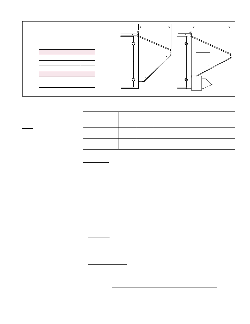
3.2.2 Dimensions
FIGURE 4 - Length of Outside Air Hoods
for MAPS
®
III, Cabinets A, B, and C, with
Option AS16 or Option AS19
Cabinet Size
X
Y
Dimensions - Inches
A
26-3/4
44
B
26-3/4
44
C
38
38
Dimensions - mm
A
679
679
B
679
679
C
965
965
Option
AS16
Outside
Air Hood
X
Option
AS19
Outside
Air Hood
Optional
Power
Exhaust
for
Building
Y
- RPBL Option - Installation - Weather Hood Assembly RPB Option - Installation - Weather Hood Assembly REDC Option - Installation - Weather Hood Assembly RECC Option - Installation - Weather Hood Assembly RDDC Option - Installation - Weather Hood Assembly RDCC Option - Installation - Weather Hood Assembly RDC Option - Installation - Weather Hood Assembly RCC Option - Installation - Weather Hood Assembly REDB Option - Installation - Weather Hood Assembly RECB Option - Installation - Weather Hood Assembly RDDB Option - Installation - Weather Hood Assembly RDCB Option - Installation - Weather Hood Assembly RDB Option - Installation - Weather Hood Assembly RCB Option - Installation - Weather Hood Assembly ADFH Option - Installation - Weather Hood Assembly ADF Option - Installation - Weather Hood Assembly