4 option as2, outside air hood (cont'd) – Reznor RBL Option - Installation - Weather Hood Assembly User Manual
Page 12
Form-I-OPT-WH, Page 12
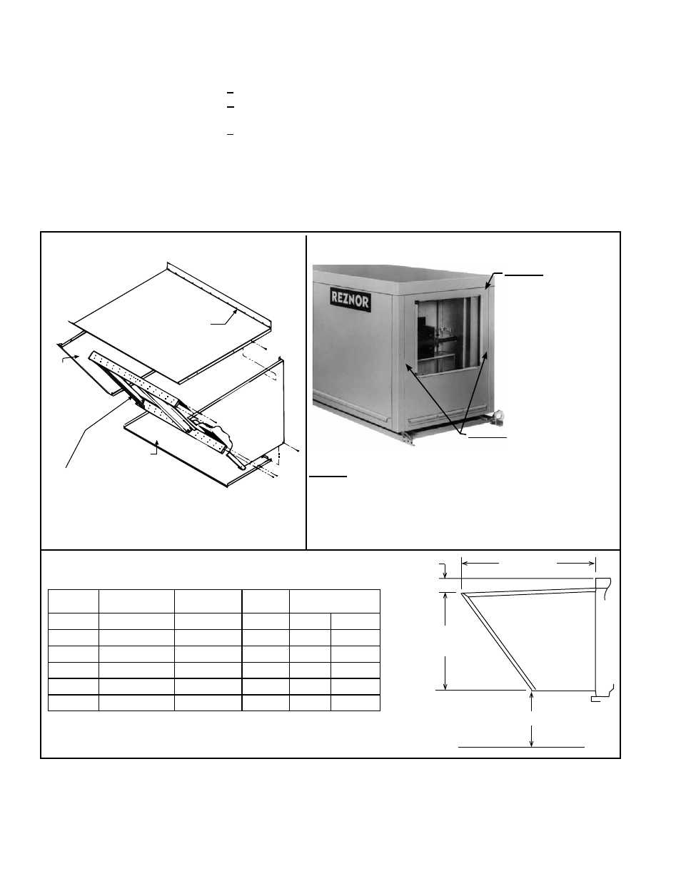
All screw ends except those across the bottom
should be inside the hood.
STEP 2 - Insert hood side
panels into slots. Attach to
cabinet and hood top panel.
STEP 1 - Remove
the row of screws
holding the top to
the cabinet end.
Slide the edge of
the hood top panel
under the cabinet
top.
Re-insert screws.
STEP 3 - If the bottom panel of the hood does not rest
tightly against the support angle, adjust the position of
the support angle:
a) Slightly loosen (do not remove) the support angle screws.
b) Slide the support angle up so that it is against the bottom panel.
Do not draw together with the screws.
c) Tighten screws.
FIGURE 8B - Inlet Air End of the Cabinet Illustrating
Locations of Installation STEPS 1, 2, and 3
Direct-fired
Model ADF
Top Panel
(edge must be
under cabinet top)
Left Side
Panel
Right
Side
Panel
Factory-assembled Louver
Assembly including Moisture
Eliminating Louvers and Screen
Bottom Panel
FIGURE 8A - Parts Identity and Assembly
Orientation
FIGURE 8C - Dimensions (inches and mm) of Installed
Outside Air Hood, Option AS2, on Models Listed
43-17/32
(1106mm)
4-5/8
(117mm)
31-11/32
(796mm)
14 (356mm) minimum
Option AS2
Screened Outside
Air Hood
with Louvers
(H)RPB
RPBL
Blower
Cabinet
ADF,
ADFH
*Width of AS2
Outside Air Hood
125
28-5/8" 727mm
150, 175
Model RBA 300
34-1/8" 867mm
200, 225
39-5/8" 1006mm
250, 300 500, 600
500
47-7/8" 1216mm
350
700, 1050
53-3/8" 1356mm
400
400, 800, 1200 Model RBL
700,1200 58-7/8" 1495mm
*The width of the outside air hood is the same as the width of the
cabinet.
3. Components,
Dimensions,
and Installation
Instructions
(cont'd)
If the bottom panel does not rest tightly against the support angle, follow these
instructions to adjust the position of the support angle:
a) Slightly loosen (do not remove) the support angle screws.
b) Slide the support angle up (holes are slotted) so that it is against the bottom
panel.
c) Tighten the screws.
Attach the support angle to the hood bottom panel. The bottom panel of the hood
and the support angle should be tight together; do not draw with the screws.
4. Install the Louver Assembly - With the intake screen toward the inside of the
hood, position the vertical louver assembly in the inlet opening of the hood. Using
the remaining sheetmetal screws, attach the louver assembly to the hood side
panels at the holes provided.
3.4.2 Installation Instructions (cont'd)
3.4 Option AS2,
Outside Air
Hood (cont'd)
- RPBL Option - Installation - Weather Hood Assembly RPB Option - Installation - Weather Hood Assembly REDC Option - Installation - Weather Hood Assembly RECC Option - Installation - Weather Hood Assembly RDDC Option - Installation - Weather Hood Assembly RDCC Option - Installation - Weather Hood Assembly RDC Option - Installation - Weather Hood Assembly RCC Option - Installation - Weather Hood Assembly REDB Option - Installation - Weather Hood Assembly RECB Option - Installation - Weather Hood Assembly RDDB Option - Installation - Weather Hood Assembly RDCB Option - Installation - Weather Hood Assembly RDB Option - Installation - Weather Hood Assembly RCB Option - Installation - Weather Hood Assembly ADFH Option - Installation - Weather Hood Assembly ADF Option - Installation - Weather Hood Assembly