2 location of piping connections at, The split system evaporator coil – Reznor MASA Unit Installation Manual User Manual
Page 8
Form I-COND, P/N 220746R6, Page 8
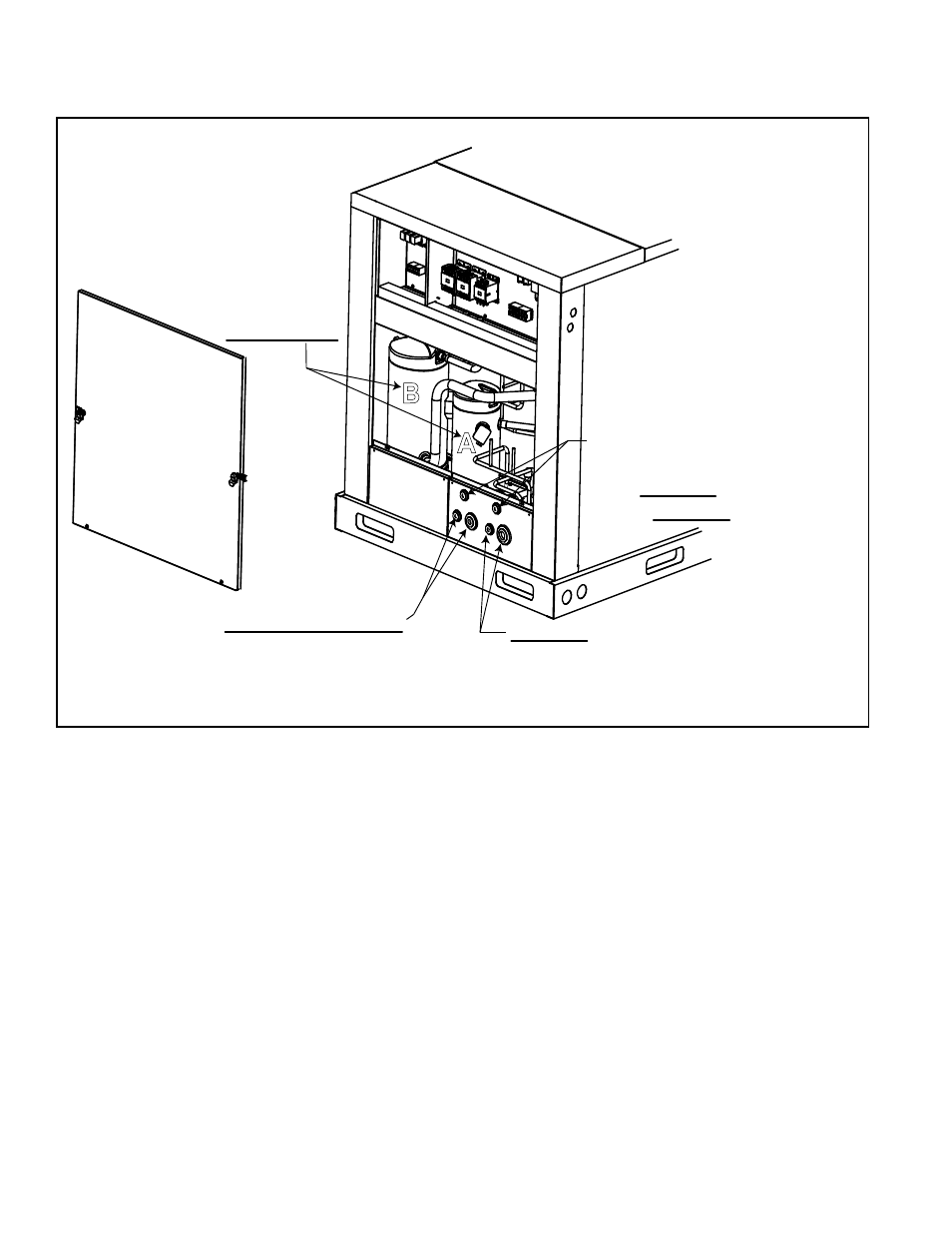
FIGURE 3 - Condensing
Unit Refrigerant Piping
Connection Locations
6.1.2 Location of Piping Connections at the Split System
Evaporator Coil
It is important to identify the Circuit A and Circuit B connections at the evapora-
tor coil before running the refrigerant lines.
Circuit A on the condenser (
FIGURE 3) is the smaller (33%) circuit and should
be connected to the 33% circuit of the evaporator coil. Circuit B on the con-
denser (
FIGURE 3) is the larger (67%) circuit and should be connected to the
67% circuit of the evaporator coil.
On the evaporator coil, identify the liquid line connection at the distributor for
the smaller circuit (Circuit A). Force nitrogen into the Circuit A connection and
check which suction line connection corresponds to it. If the suction line con-
nection is not identified, mark it as Circuit A. For verification, repeat the pro-
cess with the larger circuit and mark the suction line connection as Circuit B.
Refer to
FIGURE 4A or 4B for illustration of a split system refrigerant piping
system connecting a MASA condensing unit to a PreevA
®
evaporator coil. In
FIGURE 4A, the condensing unit is higher than the evaporator coil. In FIGURE
4B, the condensing unit is lower than the evaporator coil.
6.0 Mechanical
(cont’d)
Circuit A (1/3 circuit)
Piping Entrance Holes -
Liquid line on the left;
Suction line on the right
Electrical and
Compressor
Compartment
Access
Panel
Circuit B (2/3 circuit)
Piping Entrance Holes -
Liquid line on the left;
Suction line on the right
Entrances for Optional
Hot Gas Bypass Connections
Left - Circuit A;
Right - Circuit B
R-410A Compressors
(identified by
Circuit A & B)
B
A
Electrical
Compartment
6.1.1 Location of Piping Connections at the Condensing Unit
(cont’d)