0 location 3.0 receiving, moving, and uncrating, 1 receiving 3.2 moving 3.3 uncrating, 1 shipped-separate items – Reznor MASA Unit Installation Manual User Manual
Page 5: 0 clearances and dimensions, 1 clearances, 1 receiving, 2 moving, 3 uncrating
Form I-COND, P/N 220746R6, Page 5
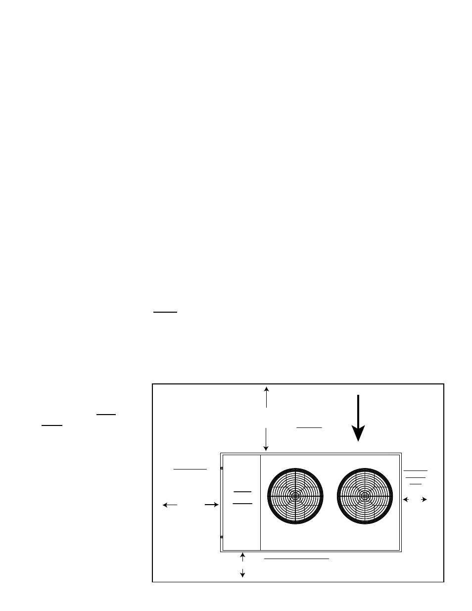
4.1 Clearances
The condensing unit must
have unrestricted airflow
FIGURE 1 - Minimum
Clearances (Top
View)
Coil Side
(Inlet airflow through
the condenser coil
must be unrestricted.)
Control Side
(Service
Clearance)
Opposite
Control
Side
Electrical Entrance Side
NOTE: Suggested side for installing disconnect switch;
see
FIGURE 2, page 6. If disconnect switch is installed
on this side, minimum clearance is 36” (914mm).
Airflow
Top discharge airflow must be unrestricted.
Top clearance is 60” (1524mm).
36”
(914mm)
6”
(152mm)
6” (152mm)
48”
(1219mm)
Top
View
on the coil side and above the unit. A service clearance is required on the con-
trol side of the cabinet.
2.0 Location
3.0 Receiving,
Moving, and
Uncrating
3.1 Receiving
Check for any damage that may have been incurred during shipment. If dam-
age is found, document the damage with the transporting agency and immedi-
ately contact your Reznor distributor. If you are an authorized Distributor, follow
the FOB freight policy procedures as published by Reznor for Reznor products.
3.2 Moving
The heavy gauge base of the condensing unit has forklift openings in both
sides. To move a unit, use a forklift with forks that have a minimum length of
24” (610mm).
3.3 Uncrating
Immediately upon uncrating, check the electrical characteristics to verify that
the unit is suitable for the installation site. This condensing unit is designed for
R-410A refrigerant only; verify that the split system air handler is for use with
R-410A refrigerant.
3.3.1 Shipped-Separate Items
Before beginning installation, be sure that all shipped-separate options ordered
are available at the site. Shipped-separate options could have been ordered
with the condensing unit or the matching PreevA
®
air handler.
NOTE: Two liquid line filter driers are shipped loose with the condensing unit
for field installation.
4.0 Clearances and Dimensions
Model MASA condensing unit must be mounted outdoors on a level surface.
The supporting structure must be able to support the operating weight of the
unit and maintain a level plane during continued operation. Water should drain
away from the unit. Location must comply with free space clearances for unre-
stricted airflow (See Paragraph 4.1) and the refrigerant piping requirements
(See Paragraph 6.1.3). Avoid facing condenser coils into the prevailing wind.