4 control wiring, 0 controls and operation, 1 analog control system 8.2 digital control system – Reznor MASA Unit Installation Manual User Manual
Page 21: 1 analog control system, 2 digital control system, Split system air handler, If connecting to a preeva, Air handler (reznor, Model sdh, pdh, or rdh). refer to the pre- eva
Form I-COND, P/N 220746R6, Page 21
TABLE 8 - 24V
Control Wiring Size
and Length
24V Field Control Wiring Length/Gauge
Total Wire Length
Distance from Unit to Control
Minimum Wire Gauge
150ft (46M)
75ft (23M)
18
250ft (76M)
125ft (38M)
16
350ft (107M)
175ft (53M)
14
7.4 Control Wiring
The condensing unit is equipped with a low voltage (24V) control circuit.
Depending on the air handler controls, the control system is either analog or
digital.
24V wires enter the cabinet just below the line voltage entrance and must be
routed over to the low voltage compartment on the left. (See
FIGURE 8, page
28.) Connections are made at the low voltage terminal blocks.
See
TABLE 8 for wiring size and length requirements.
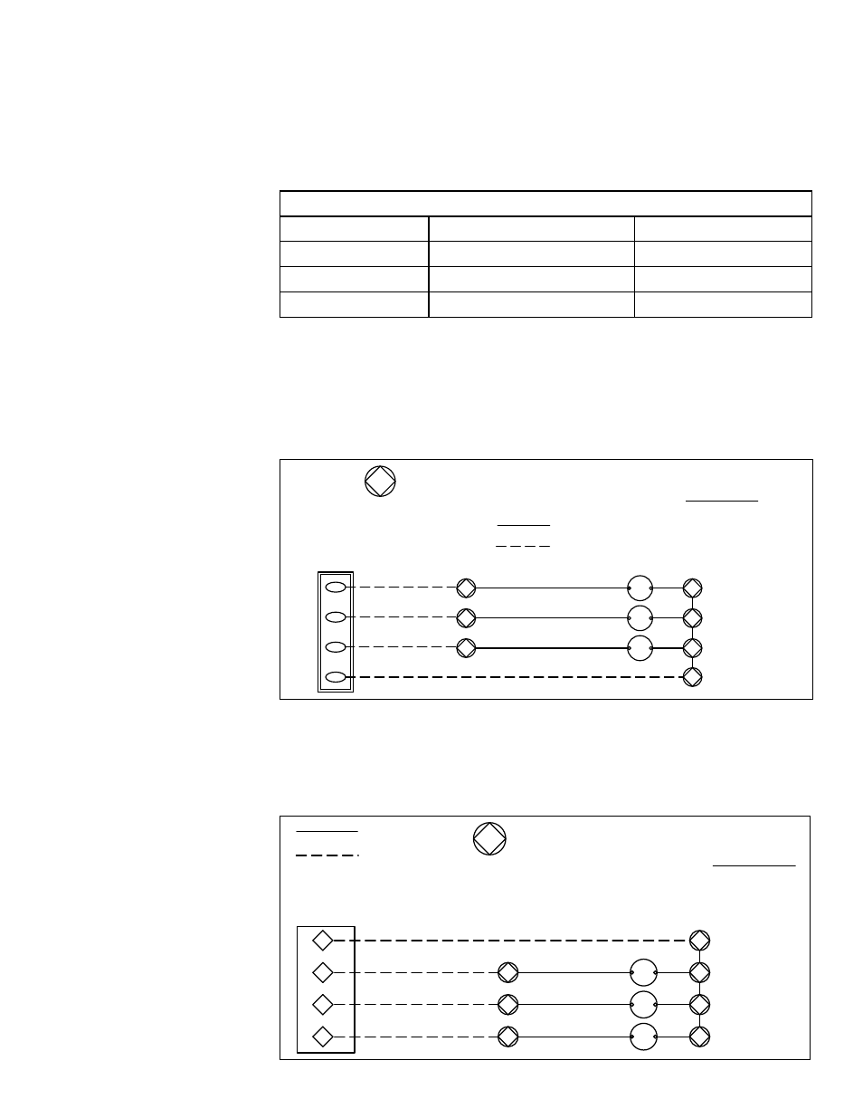
FIGURE 7A - Analog
Control Connection
Wiring Diagram
WIRING CODE
BROWN - BR
RED - R
ORANGE - O
PURPLE - PR
TERMINAL BLOCK -- LOW VOLTAGE
COMPARTMENT
UNIT
TERMINALS
7
8
X
Y1
Y2
Y3
FACTORY WIRING
FIELD WIRING
Y3
Y1
Y2
PR
O
R
T7350D THERMOST
AT
CUST
OMER'S
X
Y2
Y3
Y1
PR
8
O
R
8
8
X
2ND STAGE
RELAY COIL (CR2)
1ST STAGE
RELAY COIL (CR1)
3RD STAGE
RELAY COIL (CR3)
BR
7
CR
X
BR
BR
7
7
CR
CR
X
X
8.0 Controls and
Operation
Make control connections at the 24V terminal blocks in the low voltage elec-
trical compartment. See analog control connections in
FIGURE 7A or digital
control connections in
FIGURE 7B.
8.1 Analog Control
System
If using an analog control system, connection is to a low-voltage (24V) 3-stage
thermostat. The thermostat may be field-provided or an accessory to the air
handling unit.
8.2 Digital Control
System
If connecting to a PreevA
®
digital control system, control is from an
FX05 programmable controller located in the control compartment of the
PreevA
®
air handler (Reznor
®
Model SDH, PDH, or RDH). Refer to the Pre-
evA
®
installation manual (either Form I-PDH/SDH or Form I-RDH) for com-
plete control information.
PREEVA UNIT
(WITH FX-05 CONTROLLER)
CUSTOMER'S
63
61
62
87
Y3
Y1
Y2
PR
O
R
8
8
8
BR
7
CR
X
BR
BR
7
7
CR
CR
X
X
X
TERMINAL BLOCK -- LOW VOLTAGE
COMPARTMENT
UNIT
TERMINALS
7
8
X
Y1
Y2
Y3
FACTORY WIRING
FIELD WIRING
WIRING CODE
BROWN - BR
RED - R
ORANGE - O
PURPLE - PR
2ND STAGE
RELAY COIL (CR2)
1ST STAGE
RELAY COIL (CR1)
3RD STAGE
RELAY COIL (CR3)
FIGURE 7B - Digital
Control Connection
Wiring Diagram for a
Reznor PreevA
®
Split
System Air Handler