0 mechanical (cont’d), 1 refrigerant piping (cont’d) – Reznor MASA Unit Installation Manual User Manual
Page 12
Form I-COND, P/N 220746R6, Page 12
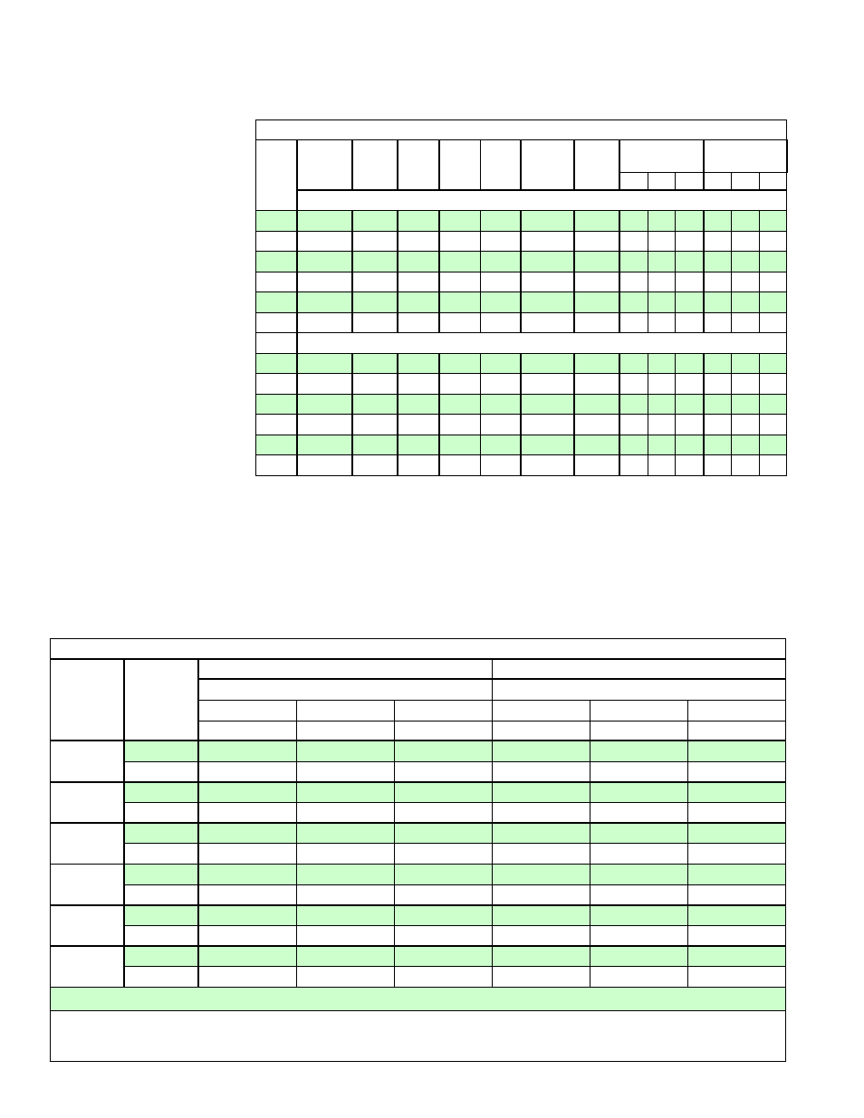
TABLE 3 -
Recommended Size
of Refrigerant Piping
for each Segment
determined by the
Equivalent Length
Use the worksheet on page 13, and the information in
TABLE 2 and TABLE 3
to determine the line segment and circuit equivalent lengths and the size
of tubing required for each line segment.
IF AN APPLICATION REQUIRES MORE THAN 60 FEET (18.3M) OF EQUIV-
ALENT LENGTH OF TUBING (LIQUID LINE OR SUCTION LINE) BETWEEN
THE CONDENSER AND THE AIR HANDLER, CONTACT REZNOR FOR
APPROVAL.
TABLE 2 - Fitting
Pressure Loss in
Equivalent Length
of Straight Copper
Tubing
Equivalent Length of Fittings and Accessories
Line
Size
OD
Globe /
Solenoid
Valve
Angle /
Check
Valve
90º SR
Elbow
90º LR
Elbow
45º
Elbow
Tee Line
/ Sight
Glass
Tee
Branch
Coupling to
Enlarge OD by
Coupling to
Reduce OD by
1/
4"
1/
2"
3/
4"
1/
4"
1/
2"
3/
4"
Equivalent Length (in Feet of Pipe)
1/2"
9
5
1.4
0.9
0.4
0.6
2.0
1.
4
0.
8
0.
3
0.
7
0.
5
0.
3
5/8"
12
6
1.5
1.0
0.5
0.8
2.5
1.
8
1.
1
0.
4
0.
8
0.
7
0.
4
3/4"
14
7
1.9
1.3
0.6
0.9
3.0
2.
5
1.
5
0.
5
1.
2
1.
0
0.
5
7/8"
15
8
2.3
1.5
0.7
1.0
3.5
3.
2
2.
0
0.
7
1.
6
1.
2
0.
7
1-1/8"
22
12
2.7
1.8
0.9
1.5
4.5
4.
7
3.
0
1.
0
2.
3
1.
8
1.
0
1-3/8"
28
15
3.6
2.4
1.2
1.8
6.0
5.
8
3.
6
2.
9
2.
9
2.
2
1.
2
Equivalent Length (in Meters of Pipe)
1/2"
2.7
1.5
0.4
0.3
0.1
0.2
0.6
0.
4
0.
2
0.
1
0.
2
0.
2
0.
1
5/8"
3.7
1.8
0.5
0.3
0.2
0.2
0.8
0.
6
0.
3
0.
1
0.
2
0.
2
0.
1
3/4"
4.3
2.1
0.6
0.4
0.2
0.3
0.9
0.
8
0.
5
0.
2
0.
4
0.
3
0.
2
7/8"
4.6
2.4
0.7
0.5
0.2
0.3
1.1
1.
0
0.
6
0.
2
0.
5
0.
4
0.
2
1-1/8"
6.7
3.7
0.8
0.6
0.3
0.5
1.4
1.
4
0.
9
0.
3
0.
7
0.
6
0.
3
1-3/8"
8.5
4.6
1.1
0.7
0.4
0.6
1.8
1.
8
1.
1
0.
9
0.
9
0.
7
0.
4
6.0 Mechanical
(cont’d)
NOTE: Liquid line filter
driers provided have 1/2”
connections. Add equil-
valent length for filter
driers plus, if liquid line is
not 1/2”, add equilvalent
for fittings.
*Minimum Recommended Refrigerant Piping Size
MASA
Model
Circuit
Suction Line Tubing Size (OD)
Liquid Line Tubing Size (OD)
**Equivalent Length of the Suction Line - Ft (M)
**Equivalent Length of the Liquid Line - Ft (M)
Up to 25 Ft
> 25 to 50 Ft
> 50 to 60 Ft
Up to 25 Ft
> 25 to 50 Ft
> 50 to 60 Ft
(Up to 7.6M)
(> 7.6 to 15.2M)
(> 15.2 to 18.3M)
(Up to 7.6M)
(> 7.6 to 15.2M)
(> 15.2 to 18.3M)
60
A
1/2
5/8
3/4
1/2
1/2
1/2
B
3/4
3/4
7/8
1/2
1/2
1/2
90
A
5/8
3/4
3/4
1/2
1/2
1/2
B
7/8
7/8
1 1/8
1/2
1/2
1/2
120
A
3/4
3/4
7/8
1/2
1/2
1/2
B
7/8
1 1/8
1 1/8
1/2
5/8
5/8
150
A
7/8
7/8
1 1/8
1/2
1/2
1/2
B
1 1/8
1 1/8
1 3/8
1/2
5/8
5/8
180
A
7/8
7/8
1 1/8
1/2
1/2
1/2
B
1 1/8
1 1/8
1 3/8
1/2
5/8
5/8
240
A
7/8
1 1/8
1 1/8
1/2
5/8
5/8
B
1 1/8
1 3/8
1 3/8
5/8
3/4
3/4
*Based on copper tubing type L; a 2°F loss; and a maximum of 65ºF suction line (return gas) temperature and liquid line temperature of 105ºF.
**Equivalent Line Segment Length = length of field-installed tubing in line segment plus equivalent length of all field-installed fittings and
accessories in line segment. For both liquid line and suction line segments, maximum recommended equivalent length is 60 ft (18.3M).
CAUTION: Maximum equivalent length of a hot gas bypass line is 30 ft (9.1M).
6.1 Refrigerant Piping (cont’d)
6.1.3 Refrigerant Piping Guidelines (R-410A Refrigerant) (cont’d)
6.1.3.2 Refrigerant Piping Length and Size (cont’d)