3 liquid line piping – Reznor MASA Unit Installation Manual User Manual
Page 13
Form I-COND, P/N 220746R6, Page 13
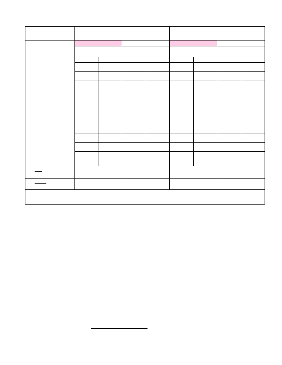
Circuit (field-installed Liquid
Line Segment and Suction
Line Segment)
CIRCUIT A (1/3 Circuit)
CIRCUIT B (2/3 Circuit)
Line Segment (field-
installed refrigerant tubing)
Liquid Line
Suction Line
Liquid Line
Suction Line
Tubing Size ________
Tubing Size ________
Tubing Size ________
Tubing Size ________
Equivalent Lengths of All
Accessories and Fittings in
the Line Segment
Component
Length
Component
Length
Component
Length
Component
Length
Subtotal of
Equivalent Lenghts of
Accessories/Fittings
Plus Actual Length of Line
Segment
Equals Equivalent Line
Segment Length
IMPORTANT Note: Recommended maximum total equivalent standard line length between the condenser and evaporator coil is 60ft
(18.3M). For line segments longer than 60ft (18.3M) equivalent length, consult Reznor for approval. CAUTION: Maximum total equivalent
length of a hot gas bypass line is 30 ft (9.1M).
WorkSHEET for calculating the equivalent length of each of the four line segments.
6.1.3.3 Liquid Line
Piping
Design the liquid lines (a line for each circuit from the condenser to the ther-
mostatic expansion valve on the appropriate distributor at the evaporator coil)
so that the pressure drop in the liquid refrigerant will not be greater than that
corresponding to an approximate 1 to 2°F of subcooling. Pressure loss of 5
psi results in a 1°F loss of subcooling temperature with R-410A refrigerant.
The total loss is the pressure drop loss through the piping and fittings plus any
additional for lift or accessories (shutoff valve, filter, etc). Pressure loss due to
lift is approximately 0.5 PSI per foot.
Each liquid line requires field installation of one of the filter driers supplied
with the unit (see instructions below and
FIGURE 4A or 4B). Filter driers are
sized for each circuit; see
TABLE 4 to match the filter drier with the circuit.
Also, it is highly recommended that each liquid line include a field-supplied
solenoid valve and a sight glass with a moisture indicator. (NOTE: Do not rely
on the sight glass for determining amount of refrigerant charge; see Paragraph
6.4 and subcooling and superheat checks in Paragraph 9.2.3 for determining
refrigerant charge. A sight glass with a moisture indicator is important because
moisture is very detrimental to an R-410A refrigerant circuit.) Install the recom-
mended field-supplied sight glass with moisture indicator downstream of the
filter drier and upstream of the thermostatic expansion valve.
Liquid Line Filter Driers - Two liquid line filter driers are shipped loose for field
installation. Match the filter drier to Circuit A or Circuit B as listed in
TABLE 4.
Follow the filter drier manufacturer’s instructions and install the correct filter
drier in each liquid line close to the condensing unit. The arrow on the drier