Reznor MASA Unit Installation Manual User Manual
Page 15
Form I-COND, P/N 220746R6, Page 15
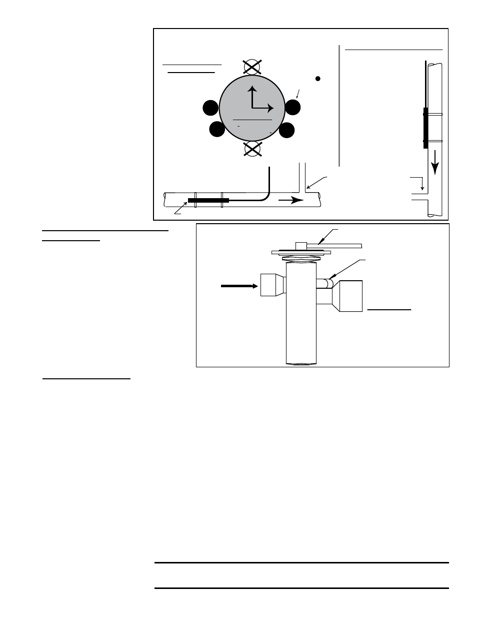
3 o’clock
4 o’clock
8 o’clock
9 o’clock
12
3
6
9
Position bulb flat against the surface of the suction line tubing. Secure bulb
tightly and insulate.
Suction Line
(Enclarged
Cross Section)
Suction Line
Thermostatic Expansion Valve (TXV) Bulb
Suction Line
Thermostatic
Expansion
Valve (TXV) Bulb
(Capillary tube should
be out the top.)
Horizontal Section
of Suction Line
(preferred location)
Vertical Section of Suction Line
(descending flow only)
Capillary
tubing
from TXV
Capillary tubing from TXV
Connect field-supplied
equalizer tubing from the TXV
(FIGURE 5B) into the
suction line a short
distance downstream
of the bulb.
Locate bulb at
one of the
positions.
FIGURE 5A - Suction
Line showing
orientation and
location of the
Thermostatic
Expansion Valve
Bulb and the
Equalizer Tubing
6.1.3.4 Suction Line
Suction Line Piping
- The suction lines (lines carrying refrigerant vapor from the evaporator to the com-
pressor) should be designed to provide minimum pressure drop and to return oil to the compressor under all
load conditions. A suction line is normally sized to have a pressure drop no greater than an approximate 2°F
of superheat.
Design and installation of the suction lines are critical to efficient operation and compressor life. Suction lines
must be insulated and pitched in direction of flow. To ensure oil return, refrigerant velocity in vertical lines
should be at least 1500 ft/minute and at least 750 ft/min in horizontal lines.
If the evaporator coil is above the condensing unit, a trap is required in the suction line as it leaves the evapo-
rator. The top of the trap must be higher than the top of the evaporator. A trap is not required and should not
be used when the condensing unit is above the evaporator.
Isolate the liquid lines from the suction lines. Insulate the entire length of each suction line.
6.1.3.5 Optional Hot
Gas Bypass Lines
Tubing for the optional hot gas bypass is field-supplied and installed. See the
illustration in
FIGURE 4A or 4B, page 9 or 10. Refer to FIGURE 3, page 6,
for location of condenser unit connection(s) and Paragraph 6.1.3.6 for braz-
ing requirements. Connect the other end of the hot gas bypass line(s) into the
corresponding circuit liquid line between the thermostatic expansion valve and
the distributor on the evaporator coil using a field-supplied auxiliary side con-
nector.
CAUTION: The maximum equivalent length of a hot gas bypass
line is 30 feet (9.1M).
Thermostatic Expansion Valve
Equalizer Line - The Model MASA
condensing unit requires thermostatic
expansion valves with an external
equalizer. To ensure that the correct
pressure is signaled to the valve,
an external equalizer line must be
connected into the
suction line
immediately
downstream of the
thermostatic expansion valve bulb
(See
FIGURE 5A).
Attach the other end of the equalizer
line to the stem on the thermostatic
expansion valve (
FIGURE 5B).
FIGURE 5B -
Thermostatic
Expansion Valve
Equalizer Line
30” (762mm) Capillary Tube
to Bulb (See FIGURE 5A)
1/4” ODF External
Equalizer Fitting
requires field-supplied
tubing connected into
the suction line just
downstream of the
TXV bulb.
Thermostatic
Expansion
Valve (TXV)
INLET
NOTE: A PreevA
®
evaporator coil ordered
with hot gas bypass has
a factory-installed side
connector for attaching
the hot gas bypass line.