0 mounting, 1 weights 5.2 lifting 5.3 mounting, 0 mechanical – Reznor MASA Unit Installation Manual User Manual
Page 7: 1 refrigerant piping, 1 location of piping connections at, The condensing unit, Caution
Form I-COND, P/N 220746R6, Page 7
5.0 Mounting
5.1 Weights
Before installing, check the supporting structure to be sure that it has sufficient
load-bearing capacity to support the operating weight of the unit. Mounting is
the responsibility of the installer.
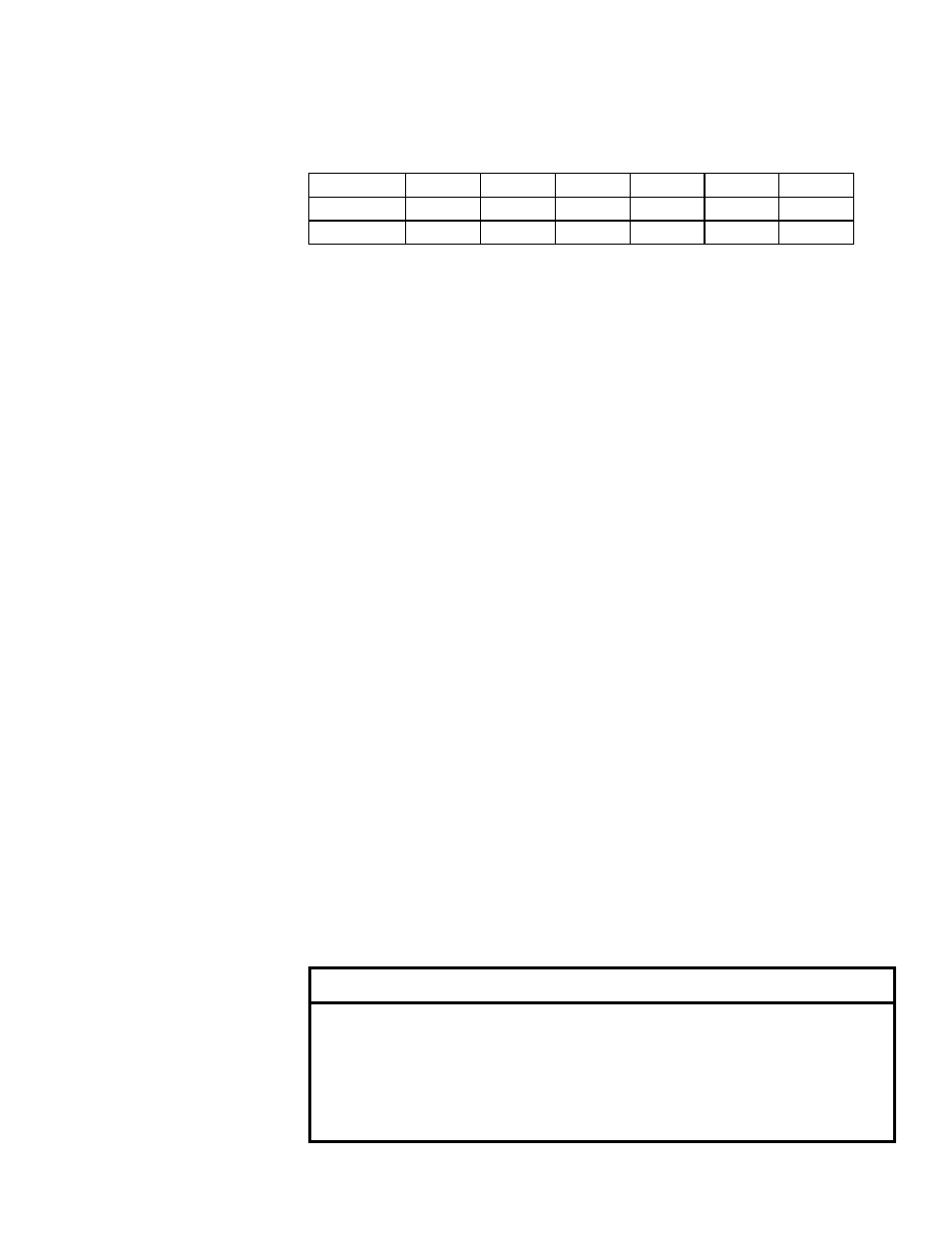
TABLE 1 - Weights
Approximate Operating Weight of Condensing Unit
MASA Size
060
090
120
150
180
240
lbs
440
461
632
699
749
771
kg
200
209
287
317
340
350
6.0 Mechanical
6.1 Refrigerant Piping
6.1.1 Location of Piping Connections at the Condensing Unit
Remove the control compartment door panel. Locate the refrigerant connec-
tions in the lower right corner. See
FIGURE 3, page 8. Each circuit is shipped
with a nitrogen charge and has a shutoff valve. Do not open the valves until
after the lines are connected and the condenser circuits are leak tested.
The entrances for the two main refrigerant circuits are identified as Circuit A
and Circuit B (See
FIGURE 3). Circuit A is the smaller (approximate 33%) con-
denser circuit; Circuit B is the larger (approximate 67%) circuit. Also indicated,
are the entrances for optional hot gas bypass circuits. If the condensing unit
is equipped with a hot gas bypass on only one circuit (Option CUG2), only
one entrance will be used. If equipped with a hot gas bypass on both circuits
(Option CUG3), both entrances will be used.
When connecting refrigerant
lines to the condensing unit and the air handler, it is very important to
make all connections so that each individual circuit is maintained.
5.2 Lifting
The heavy gauge base of the condensing unit has fork lift holes and a pair of
lifting holes on each corner for rigging. If lifting with a forklift, forks must have
a minimum length of 24” (610mm). If attaching rigging, insert a clevis in each
set of holes for the rigging
and lift using spreader bars. Lift the unit straight
up with vertical force.
Test lift the unit to be sure that it is secure and then lift slowly following safe
lifting procedures. Lifting and rigging are the responsibility of the installer.
5.3 Mounting
Condensing unit may be set directly on a roof or slab. Unit must be level. Be
sure to comply with clearances in
FIGURE 1, page 5.
CAUTION
Do not remove seal caps from refrigerant connections or
open the service valves until ready to make permanent
connection. Exposure to the atmosphere for longer than
five minutes may allow moisture and dirt to contaminate the
system. See Hazard Levels, page 3.