2 dimensions, 0 clearances and dimensions cont’d), Masa sizes 60 and 90 – Reznor MASA Unit Installation Manual User Manual
Page 6
Form I-COND, P/N 220746R6, Page 6
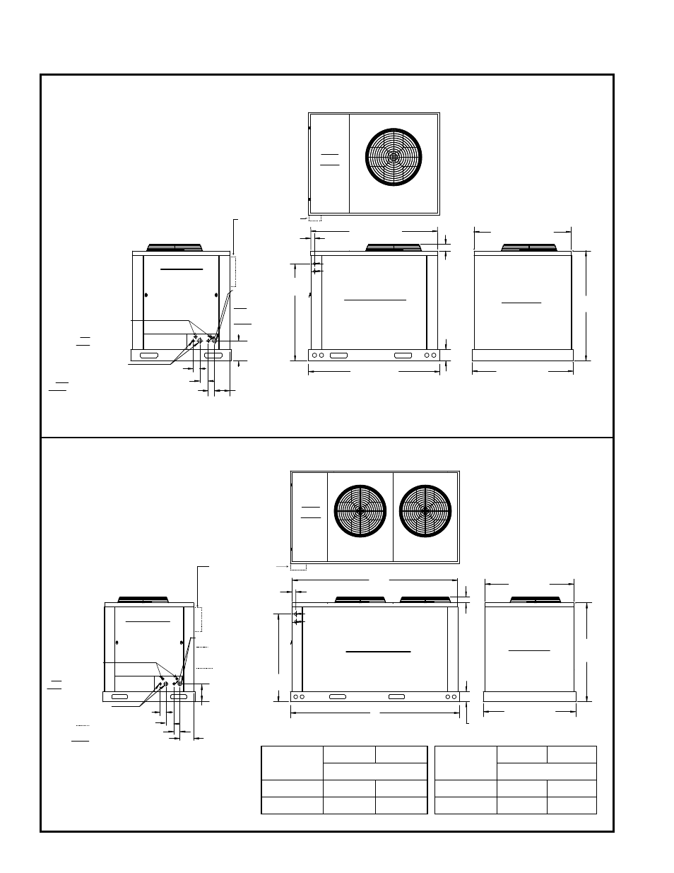
FIGURE 2A - Model MASA 60 and 90 Dimensions
61” (1549mm)
59” (1499mm)
9-5/32”
(233mm)
47”(1194mm)
50-1/4”
(1273mm)
5-1/8”
(130mm)
7” (178mm)
3” (76mm)
3” (76mm)
4” (102mm)
45-7/32” (1149mm)
44-13/32”
(1128mm)
1-25/32”
(45mm)
3”
(76mm)
Supply Voltage Entrance
Control Voltage Entrance
Electrical Box
and Compressor
Compartment
Access Panel
CIRCUIT B
Connections
Left - 1/2”
Liquid Line;
Right - 7/8”
Suction Line
Optional Hot Gas
Bypass Connections
Left - Circuit A, 1/2”
Right - Circuit B, 1/2”
CIRCUIT A
Connections
Left - 1/2” Liquid Line;
Right - 7/8” Suction Line
Front View
Right Side View
(side opposite coil)
Rear View
Top
View
MASA Sizes
60 and 90
Suggested location
for field-installed
disconnect switch
(See FIGURE 1, page 5.)
A
B
47” (1194mm)
50-1/4”
(1273mm)
5-1/8”
(130mm)
45-7/32”
(1149mm)
3”
(76mm)
44-13/32”
(1128mm)
1-25/32”
(45mm)
Supply Voltage Entrance
Electrical Box
and Compressor
Compartment
Access Panel
7” (178mm)
3” (76mm)
3” (76mm)
9-5/32”
(233mm)
4” (102mm)
Front View
Right Side View
(side opposite coil)
Top
View
MASA Sizes
120, 150, 180, 240
Rear View
CIRCUIT A
Connections
Left - 1/2”
Liquid Line;
Right - 7/8”
Suction Line
CIRCUIT B Connections
Left - Liquid Line, 1/2”
Sizes 120, 150, 180;
5/8” Size 240
Right - Suction Line,
7/8” Size 120; 1-3/8”
Sizes 150, 180, 240
Control Voltage Entrance
Optional Hot Gas
Bypass Connections
Left - Circuit A, 1/2”
Right - Circuit B, 1/2”
Suggested location
for field-installed
disconnect switch
(See FIGURE 1, page 5.)
FIGURE 2B - Model MASA 120, 150, and 180 Dimensions
MASA
Sizes
A
B
MASA
Sizes
A
B
Dimensions (inches)
Dimensions (mm)
120, 150
86
84
120, 150
2184
2134
180, 240
110
108
180, 240
2794
2743
4.0 Clearances and
Dimensions cont’d)
4.2 Dimensions