Proheat M80 User Manual
Page 71
PROHEAT G-I PCM SERVICE MANUAL
4-40
c)
Disconnect the Datalink harness at the G-I PCM. Using a multimeter set
for voltage, measure across pins D and B in the PCM Datalink connection.
If voltage is read and it is of the correct value, the fuse is OK.
If voltage is not present, check the G-I PCM fuse.
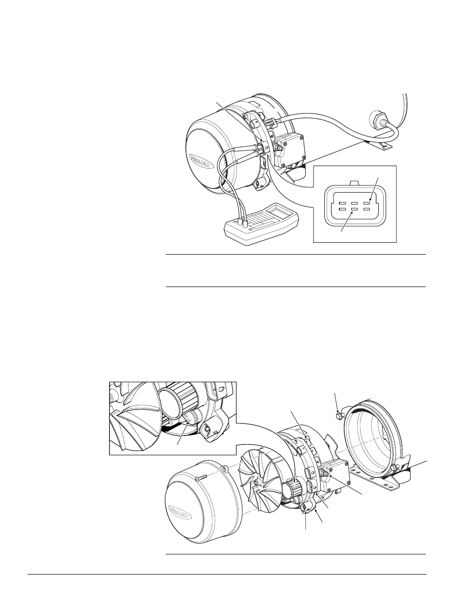
Procedure – G-I PCM fuse replacement:
a)
Disconnect all harnesses at the G-I PCM.
b)
Disconnect the fuel supply line.
c)
Loosen and back out the burner head mounting (2) bolts five to six turns
allowing enough room to rotate the burner head 15° counter-clockwise
and remove.
d)
Remove blower housing (2) screws and blower housing.
MOUNTING BOLTS (2) TORQUE = SEE SECTION 1.3
COOLANT PUMP
SWITCH INPUT
TEMP SENSOR 1
POWER
FUEL INLET
Figure 4-47: Burner Head Removal and Motor Mechanical Check
Figure 4-46: G-I PCM Datalink Connection
G-I PCM DATALINK
CONNECTION
F
D
E
A
C
B
RED (+)
BLACK (-)
FUSE COVER AND FUSE