Warning – Proheat M80 User Manual
Page 54
PROHEAT G-I PCM SERVICE MANUAL
4-23
d)
Disconnect the Ignition Module connector at the G-I PCM.
e)
Check for contamination on the Flame Sensor. Clean if necessary using
electrical contact cleaner or warm soapy water.
f)
Reconnect the power harness and the remote test switch with the switch
in the off position.
g)
Place a finger over the sensor port located on the burner head flange.
The indicator light should go out. Remove your finger and shine a flashlight
into the sensor, the remote switch indicator light should come on.
If the indicator light reacts correctly, the Flame Sensor is OK. Go to Test
Procedure – Combustion Tube orientation.
If the indicator light does not react, the Flame Sensor is faulty. Go to G-I
PCM replacement, page 4-41.
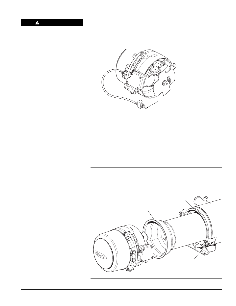
Test Procedure – Combustion Tube orientation:
a)
Ensure that the combustion tube orientation boss is aligned with the
heat exchanger flange notch.
b)
Ensure that the combustion tube 'slits' are clean.
Figure 4-28: Combustion Tube Orientation
ORIENTATION BOSS
HEAT EXCHANGER FLANGE NOTCH
MOUNTING BOLTS
TORQUE = SEE SECTION 1.3
REMOTE TEST SWITCH IN
OFF POSITION (P/N PK0091)
WARNING
To avoid the risk of shock and to
ensure that the PROHEAT does not
fire, disconnect the Ignition Module
connector at the G-I PCM.
Figure 4-27: Remote Test Switch Connection