Warning, Notice – Proheat M80 User Manual
Page 42
PROHEAT G-I PCM SERVICE MANUAL
4-11
Fuel Regulator – Check:
a)
For damage and/or contamination and mechanical operation.
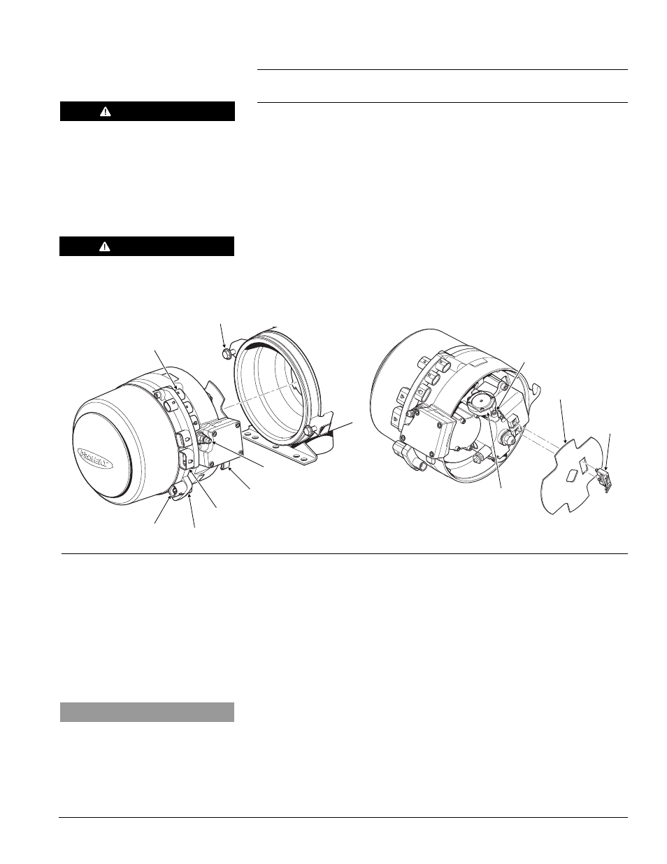
Procedure – Fuel Regulator removal, inspection and reinstallation:
a)
Disconnect all harnesses at the G-I PCM.
b)
Disconnect the fuel supply line.
c)
Loosen and back out the burner head mounting (2) bolts five to six turns
allowing enough room to rotate the burner head 15° counter-clockwise
and remove.
d)
Remove ignition electrode assembly. Use a flat head screwdriver to pry
the electrode assembly out.
e)
Remove the flame shield. Rotate to match the mounting square.
f)
Remove the Fuel Regulator (2) screws, Fuel Regulator and O-rings.
g)
Inspect O-rings and O-ring seats for contamination and/or damage.
Replace if necessary.
h)
Reinstall regulator ensuring that the O-rings are seated properly.
i)
Reinstall the burner head by mounting it against the heat exchanger face,
turning clockwise to engage the mounting ears on the bolts.
j)
Reconnect the electrical harnesses and fuel supply line.
k)
Switch the PROHEAT on and operate for at least one complete cycle.
Observe the operation.
If a Start diagnostic code is indicated, proceed to Step 6.
START: Fuel System Step 5
(1 Flash)
MOUNTING SCREWS (2)
TORQUE = SEE SECTION 1.3
FUEL REGULATOR
Figure 4-13: Burner Head Removal and Fuel Regulator Removal
FLAME SHIELD
IGNITION
ELECTRODE
ASSEMBLY
WARNING
Flammable.
WARNING
DO NOT disassemble the regulator.
No user serviceable parts. Attempts
to open or repair may lead to unsafe
operation.
MOUNTING EARS (2)
MOUNTING BOLTS (2)
TORQUE = SEE SECTION 1.3
COOLANT PUMP
SWITCH INPUT
TEMP SENSOR 1
POWER
FUEL INLET
NOTICE
All plugs/harnesses must be rein-
stalled into the Proheat Control
Module (G-I PCM) before heater goes
back into service.