Warning – Proheat M80 User Manual
Page 44
PROHEAT G-I PCM SERVICE MANUAL
4-13
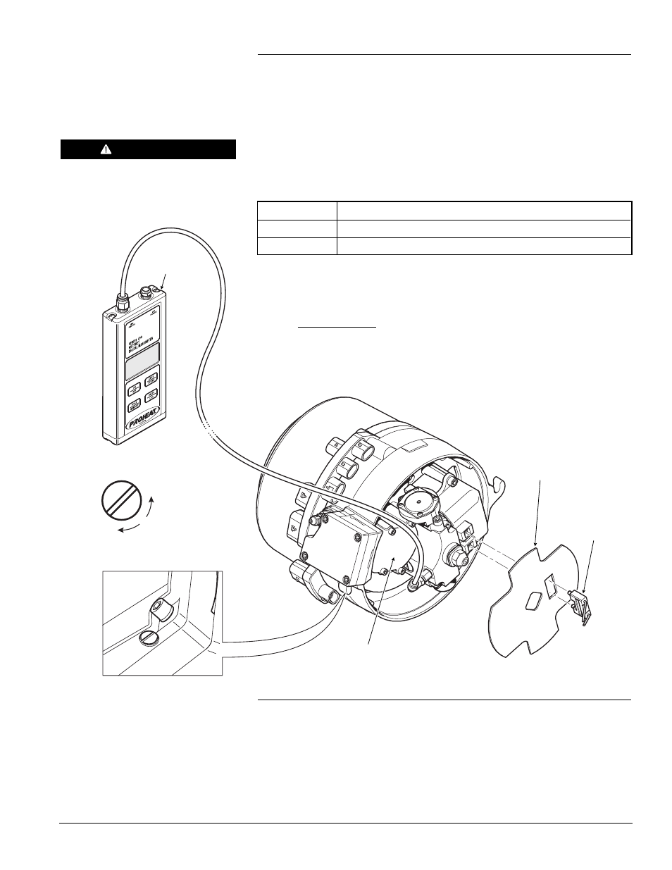
PRESSURE ADJUSTMENT SCREW
DECREASE
PRESSURE
INCREASE
PRESSURE
FLAME
SHIELD
DIAPHRAGM
COMPRESSOR
IGNITION
ELECTRODE
ASSEMBLY
Figure 4-15: Air Pressure Test. Diaphragm Compressor Model.
MODEL
AIR PRESSURE (DIAPHRAGM COMPRESSOR)
M50
6.0 ± 0.1 PSI (41.4 ± 0.7 kPa)
M80
2.9 ± 0.1 PSI (20.0 ± 0.7 kPa)
Test Procedure – Air Compressor pressure (Diaphragm Compressor models):
h)
Remove the plug to the air pressure measurement port.
i)
Thread in the Pressure Gauge and torque to 25 in-lbs ±3 in-lbs (2.8 Nm
±0.3 Nm) as shown in Figure 4-15.
j)
Connect Power Harness and Remote Switch to the G-I PCM.
k)
Switch the PROHEAT on and observe the air pressure:
If the Air Compressor reading is out of range, ensure the air compressor
filter is clean. See page 4-12.
l)
Adjust the air pressure if necessary by turning the screw as shown in
Figure 4-15.
If the pressure cannot be set to the correct setting, rebuild kits are available.
See www.proheat.com for the latest parts manual SL9151 for more information.
m) Turn heater off. Wait until purge mode is complete (approximately 3 minutes).
WARNING
Connect power and switch only. DO
NOT connect the temperature sensor.
DIGITAL
MANOMETER
(P/N PK0036)
n)
Remove Pressure Gauge. Lubricate air measurement port plug o-ring with
diesel fuel and reinstall plug into fuel block. Torque to 25 in-lbs ±3 in-lbs
(2.8 Nm ±0.3 Nm). Re-install the Flame Shield, the Ignition Ignition
Electrode Assembly and Burner Head onto the Heat Exchanger.