Notice, Warning – Proheat M80 User Manual
Page 43
PROHEAT G-I PCM SERVICE MANUAL
4-12
Air Compressor – Check:
a)
Air Compressor pressure and operation.
Before checking air pressure, remove, disassemble and clean Fuel
Nozzle. Go to Fuel Nozzle disassembly, inspection, cleaning and
reassembly, page 4-6.
Air Compressor filter check:
a)
Remove blower housing (2) screws and blower housing.
b)
Remove the Air Compressor filter. Inspect for contamination and replace
if necessary. Ensure filter is installed and seated properly.
START: Fuel System Step 6
(1 Flash)
NOTICE
Leaving the Temperature Sensor(s)
disconnected ensures that the burner
head will only run in purge for a
maximum of three minutes.
WARNING
To avoid the risk of shock and to
ensure that the PROHEAT does not
fire, disconnect the Ignition Module
& Fuel Solenoid connector at the
G-I PCM.
Test Procedure – Air Compressor pressure (all models):
a)
Disconnect all harnesses at the G-I PCM.
b)
Disconnect the fuel supply line.
c)
Loosen and back out the burner head mounting (2) bolts five to six turns
allowing enough room to rotate the burner head 15° counter-clockwise
and remove.
d)
Remove Ignition Electrode Assembly. Use a flat head screwdriver to pry
the electrode assembly out.
e)
Remove the Flame Shield. Rotate to match the mounting square.
f)
Disconnect the Fuel Shut-off Valve and Ignition Module connectors at the
G-I PCM. This ensures that fuel will not spray and/or light during testing.
g)
For Diaphragm Compressor pressure check and setting, please continue
below. For Rotary Vane Compressor pressure check and setting, please
go to page 4-14.
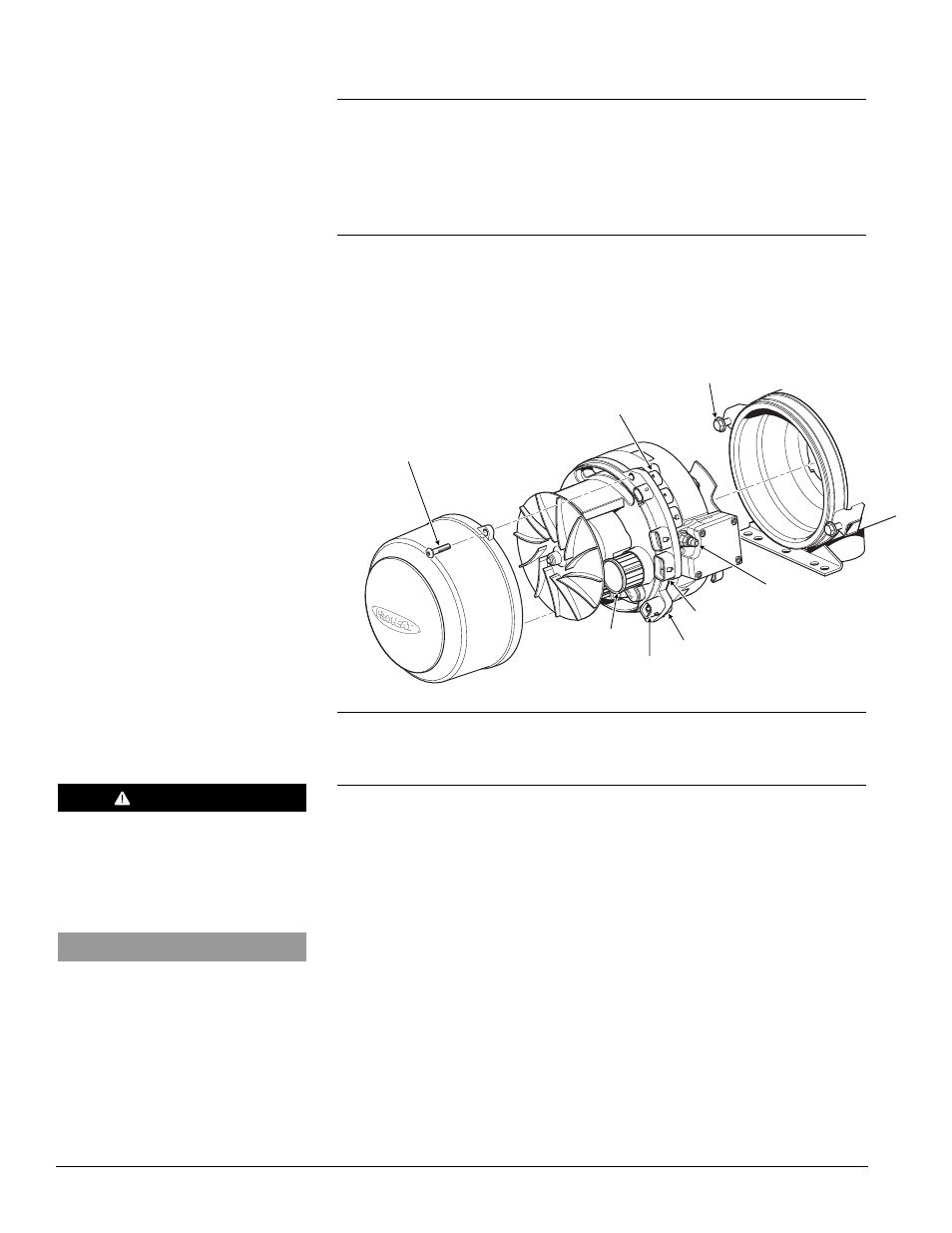
MOUNTING BOLTS (2)
TORQUE = SEE SECTION 1.3
COOLANT PUMP
SWITCH INPUT
TEMP SENSOR 1
POWER
FUEL INLET
AIR FILTER
HOUSING SCREWS
TORQUE = SEE SECTION 1.3
Figure 4-14: Burner Head and Blower Housing Removal