Warning, Ignition module – check, Start: ignition system – Proheat M80 User Manual
Page 51
PROHEAT G-I PCM SERVICE MANUAL
4-20
Ignition Module – Check:
a)
Ignition Operation using Ignition mode.
b)
Ignition Module and G-I PCM – electrical open circuit fault.
Test Procedure – Ignition service diagnostic:
a)
Disconnect all harnesses at the G-I PCM.
b)
Disconnect the fuel supply line.
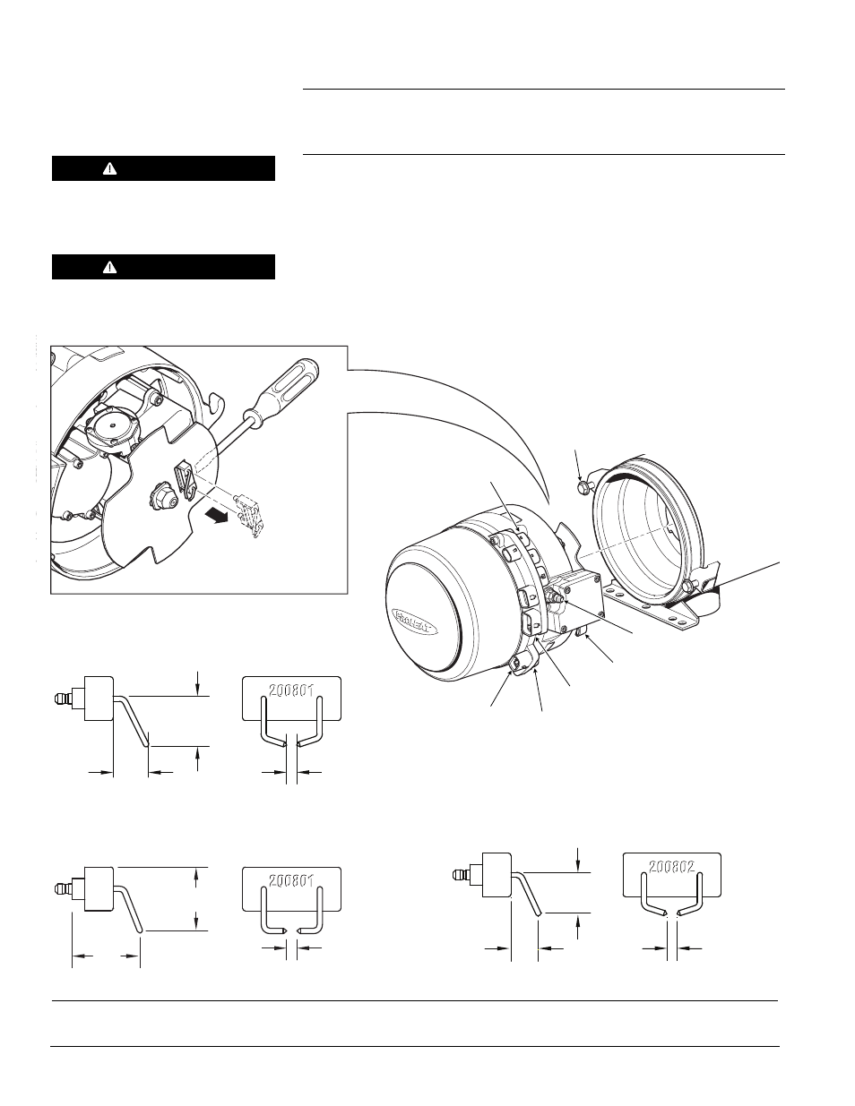
c)
Loosen and back out the burner head mounting (2) bolts five to six turns
allowing enough room to rotate the burner head 15° counter-clockwise
and remove.
d)
Check Electrodes for carbon bridging and/or damage. Replace if necessary.
START: Ignition System
(1 Flash)
WARNING
Shock hazard due to high voltage.
WARNING
Do not connect Temperature
Sensor to avoid flame.
Figure 4-22: Burner Head Removal and Ignition Electrode Removal
MOUNTING EARS (2)
MOUNTING BOLTS (2)
TORQUE = SEE SECTION 1.3
COOLANT PUMP
SWITCH INPUT
TEMP SENSOR 1
POWER
FUEL INLET
5/32" [4 mm]
3/4"
[19 mm]
17/32"
[13.5 mm]
.173" [4.4 mm]
.935"
[23.5 mm]
1.055"
[26.8 mm]
5/32" [4 mm]
5/8"
[15.9 mm]
13/32" [10.7 mm]
IGNITION ELECTRODE PID# 200801
ROTARY VANE COMPRESSOR:
500000 – 699999
IGNITION ELECTRODE PID# 200801-1
DIAPHRAGM OR ROTARY VANE COMPRESSOR:
500000 – TO DATE
IGNITION ELECTRODE PID# 200802
DIAPHRAGM OR ROTARY VANE COMPRESSOR:
700000 – TO DATE