Flame sensor – check, Start: g-i pcm flame sensor circuit – Proheat M80 User Manual
Page 53
PROHEAT G-I PCM SERVICE MANUAL
4-22
f)
Reconnect Ignition Module connector at the G-I PCM.
Flame Sensor – Check:
a)
Flame Sensor operation.
b)
Combustion tube orientation.
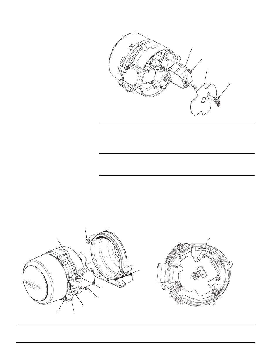
Test Procedure – Flame Sensor circuit:
a)
Disconnect all harnesses at the G-I PCM.
b)
Disconnect the fuel supply line.
c)
Loosen and back off the burner head mounting (2) bolts five to six turns
allowing enough room to rotate the burner head 15° counter-clockwise
and remove.
START: G-I PCM Flame
Sensor Circuit
(1 Flash)
Figure 4-26: Burner Head Removal and Flame Sensor Location
FLAME SENSOR PORT
MOUNTING EARS (2)
MOUNTING BOLTS (2)
TORQUE = SEE SECTION 1.3
COOLANT PUMP
SWITCH INPUT
TEMP SENSOR 1
POWER
FUEL INLET
Figure 4-25: Ignition Module Replacement
IGNITION MODULE
SCREWS (2)
TORQUE = SEE SECTION 1.3
FLAME SHIELD
IGNITION ELECTRODE
ASSEMBLY