Switch/timer power diagnostic code 14, Auxiliary output diagnostic code 13, Notice – Proheat M80 User Manual
Page 69
PROHEAT G-I PCM SERVICE MANUAL
4-38
4.1.15
(14 Flashes)
SWITCH/TIMER POWER Diagnostic Code 14
Indicates a short circuit fault in harness or the device being operated by the
Switch Output.
Troubleshoot the Switch/Timer Power diagnostic code based on:
Electrical switch circuit in the switch wiring.
Test procedure electrical, short circuit:
a)
Remove the Switch Output harness at the G-I PCM.
b)
Remote start the PROHEAT using the PROHEAT remote start switch
(PROHEAT P/N PK0091).
If the PROHEAT functions correctly, the fault is in the wiring from the
PROHEAT back to the switch. See OEM recommended service requirements.
If the PROHEAT does not function, the G-I PCM is faulty. Go to G-I PCM
replacement, page 4-41.
AUXILIARY OUTPUT Diagnostic Code 13
Indicates a short circuit fault in the harness or the device being operated by
the Auxiliary Output.
Troubleshoot the Auxiliary Output diagnostic code based on:
G-I PCM – electrical
Test procedure – G-I PCM Output Signal:
a)
Disconnect the Auxiliary Output harness at the G-I PCM.
b)
Switch the PROHEAT on and operate for at least one complete cycle.
Observe the operation.
If the diagnostic code is not indicated the fault is in the harness or the
driven device. Go to OEM for service requirements.
If the diagnostic code is still indicated, the G-I PCM is faulty. Go to G-I
PCM replacement, page 4-41.
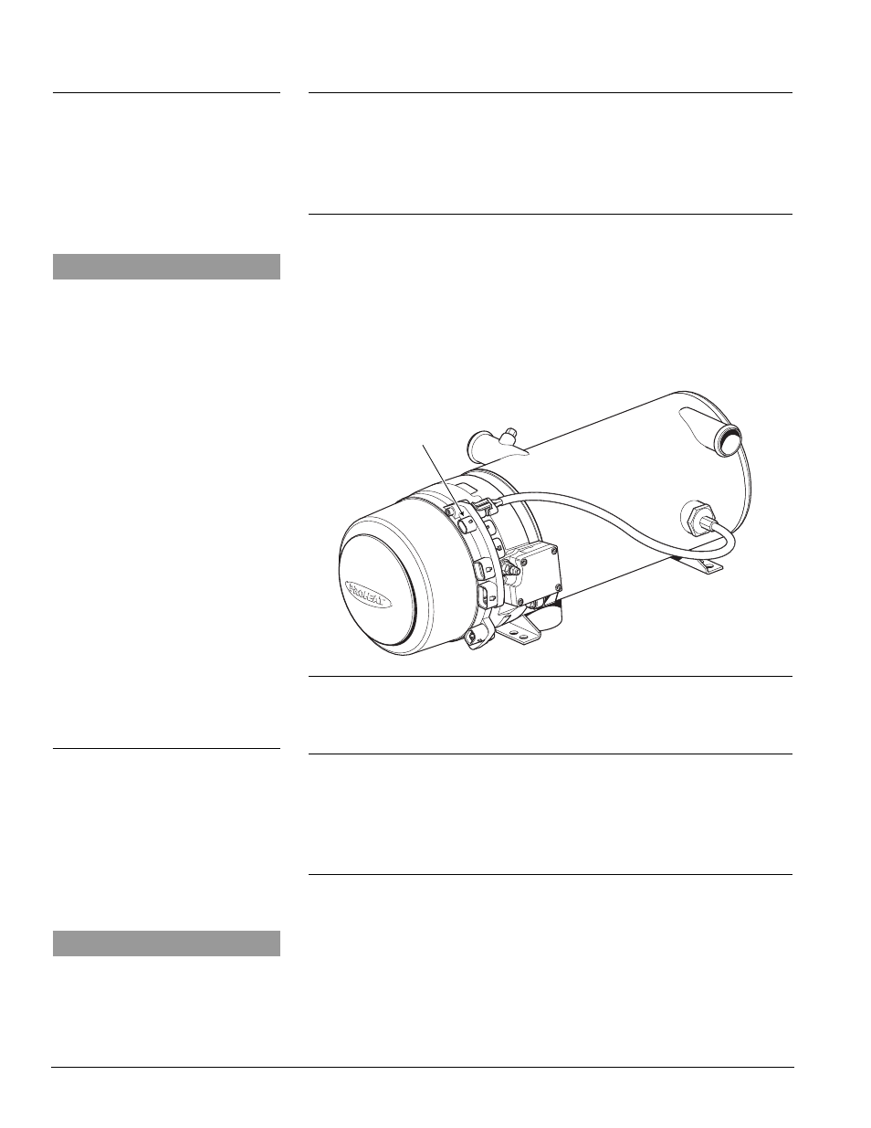
Figure 4-44: Auxiliary Output Connector
G-I PCM AUXILIARY OUTPUT
CONNECTION
4.1.14
(13 Flashes)
NOTICE
All plugs/harnesses must be rein-
stalled into the Proheat Control
Module (G-I PCM) before heater goes
back into service.
NOTICE
All plugs/harnesses must be rein-
stalled into the Proheat Control
Module (G-I PCM) before heater goes
back into service.