Caution, Notice – Proheat M80 User Manual
Page 55
PROHEAT G-I PCM SERVICE MANUAL
4-24
Motor or G-I PCM – Check:
a)
Electrical function – Open circuit motor.
b)
Electrical function – Open circuit G-I PCM.
Test Procedure – Open circuit Motor:
a)
Disconnect the Motor connector at the G-I PCM.
b)
Using a multimeter set for resistance (Ohms) measure across pins A and B.
c)
Check for an open circuit.
If an open circuit is detected, go to Motor replacement, page 4-25.
If an open circuit is not detected, go to Test Procedure – Open circuit G-I PCM.
Test Procedure – Open circuit G-I PCM:
a)
Disconnect the Motor connector and Temperature Sensor 1 at the G-I PCM.
b)
Reconnect the power and switch harnesses at the G-I PCM.
c)
Switch the PROHEAT on and measure voltage across pins A and B of the G-
I PCM Motor connection.
If the correct nominal system voltage (12 or 24) is measured, the G-I PCM
is OK. Go to Test Procedure – Open circuit Motor.
If no voltage is measured, the G-I PCM is faulty. Go to G-I PCM replacement,
page 4-41.
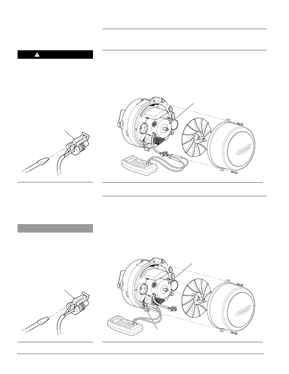
Figure 4-30: Motor Electrical Resistance Measurement
MOTOR
Figure 4-32: G-I PCM Motor Output Voltage Measurement
LOCK
Figure 4-31: Connector Removal
LOCK
Figure 4-29: Connector Removal
G-I PCM MOTOR CONNECTION
MOTOR
START: Motor and/or
G-I PCM fault
(1 Flash)
CAUTION
DO NOT connect Motor directly to
batteries or another power source
as it will damage the Motor.
NOTICE
All plugs/harnesses must be rein-
stalled into the Proheat Control
Module (G-I PCM) before heater goes
back into service.