Proheat M80 User Manual
Page 46
PROHEAT G-I PCM SERVICE MANUAL
4-15
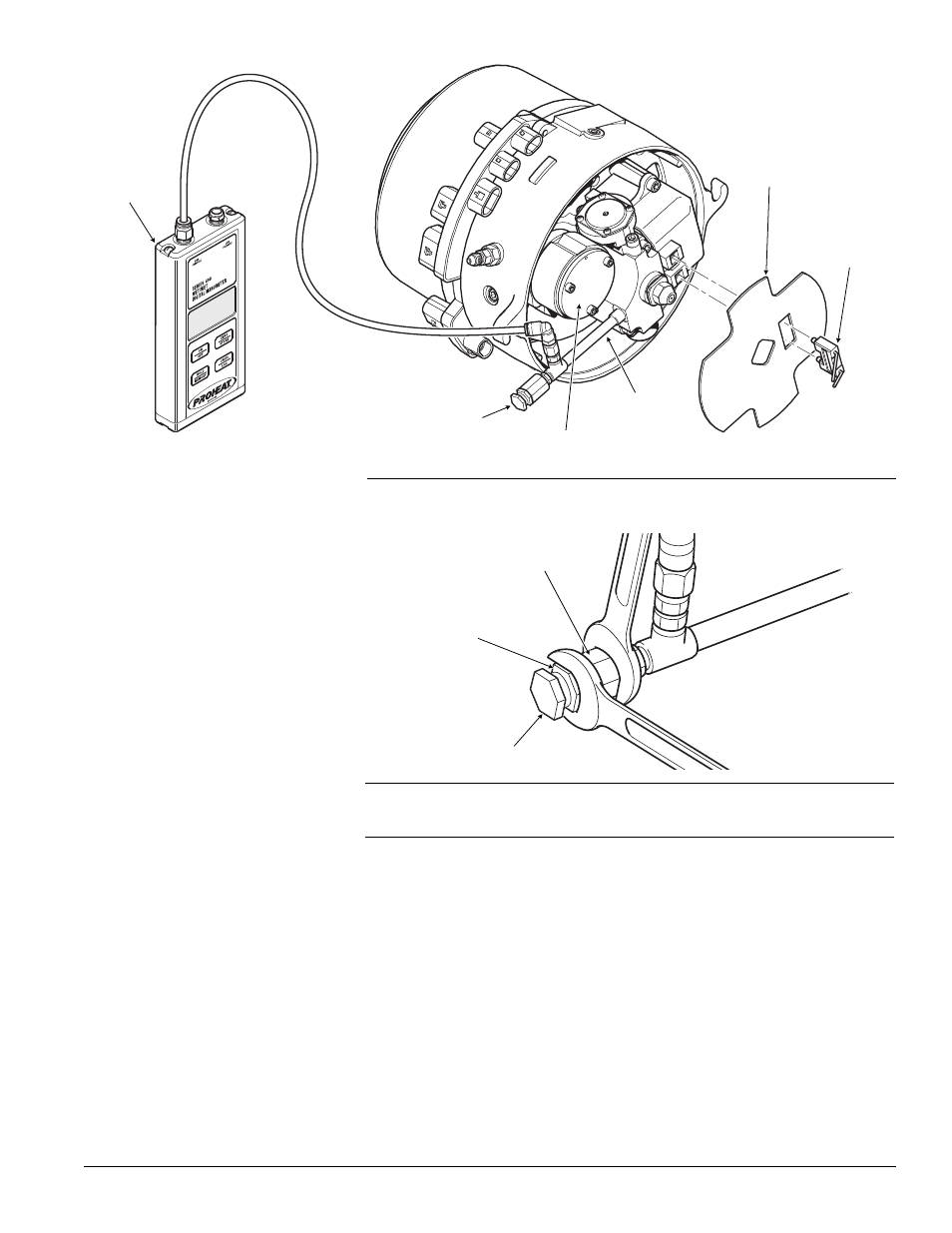
Figure 4-17: Pressure Relief Valve adjustment.
PRESSURE RELIEF CAP
LOCK NUT
PRESSURE RELIEF
VALVE BODY
PRESSURE
GAUGE
ADAPTER
ROTARY VANE
COMPRESSOR
PRESSURE
RELIEF VALVE
FLAME
SHIELD
IGNITION
ELECTRODE
ASSEMBLY
Figure 4-16: Air Pressure Test. Rotary Vane Compressor Model.
Rotary Vane Air Compressor Removal and Reassembly:
a)
Disconnect Motor, Fuel Shut-off Valve and Ignition Module connectors at
the G-I PCM.
b)
Remove blower housing (2) screws and blower housing.
c)
Remove blower retaining snap ring and slide the blower off the Motor shaft.
d)
Remove the G-I PCM.
e)
Remove Motor (4) screws and slide the Motor shaft out of the Fuel
Supply Pump taking care not to damage the Fuel Supply Pump seal.
Note the Motor drive gear size and location for reassembly.
f)
Remove the Air Compressor gear retaining snap ring and gear. Inspect
gears and replace if necessary. If gears are worn out it is not necessary
to replace compressor (spin and check for mechanical interference).
g)
Remove Air Compressor (2) screws, Air Compressor, (2) O-rings and the
gear locating snap ring from the Air Compressor shaft.
h)
Install new Air Compressor; ensure that the O-ring and seats are clean
and dry. Assembly lubricant not required.
DIGITAL
MANOMETER
(P/N PK0036)