Warning, Notice – Proheat M80 User Manual
Page 64
PROHEAT G-I PCM SERVICE MANUAL
4-33
Temperature Sensor replacement:
a)
Isolate the coolant system at the PROHEAT inlet and outlet ports for
minimal coolant loss using valves in the system or hose clamps.
b)
Remove main sensor mount using a 1" wrench and/or secondary sensor
using a 13 mm wrench.
c)
Reinstall the new sensor. Ensure that the O-ring and O-ring seat are
clean. Install the sensor until it bottoms out on the mounting boss.
WARNING
NEVER remove coolant lines when
the engine is hot – escaping steam
or scalding water could cause
serious personal injury. Loosen the
coolant line clamps slowly,
allowing the pressure to escape
before removing completely.
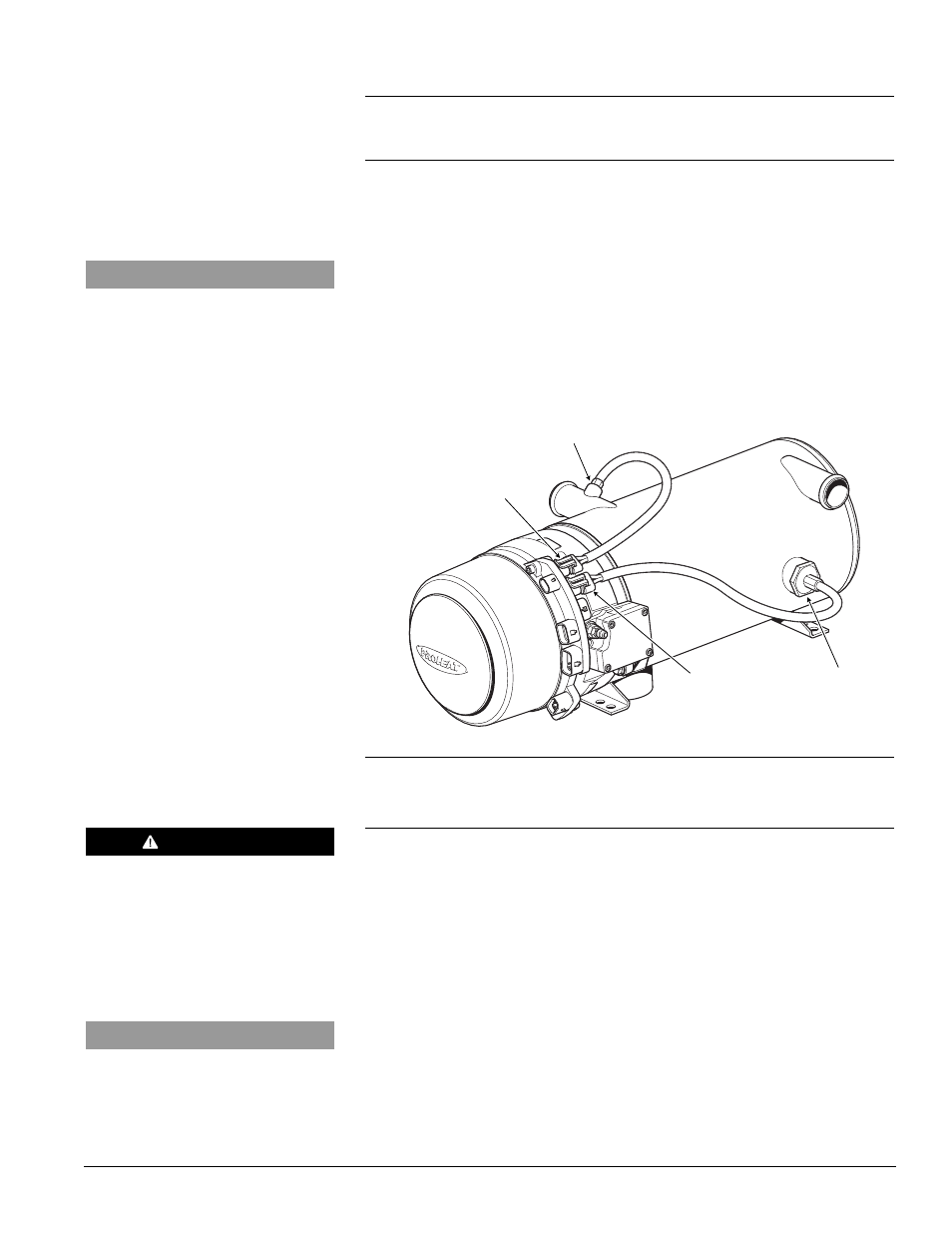
Figure 4-39: Temperature Sensors
T1
T2
TEMP SENSOR T1: Step 2
(7 or 9 Flashes)
MAIN SENSOR
TORQUE = SEE
SECTION 1.3
SECONDARY SENSOR
(IF EQUIPED) TORQUE TO
50 in-lbs ±5 in-lbs
(5.6 Nm ±0.5 Nm)
Temperature Sensor and G-I PCM electrical (dual sensors) – Check:
a)
Temperature Sensor and G-I PCM electrical function.
Test Procedure – Sensor and G-I PCM:
a)
Remove Temperature Sensor connector from G-I PCM connection T1.
b)
Remove Temperature Sensor connector from G-I PCM connection T2.
c)
Swap the connectors. T1 to T2 and T2 to T1.
d)
Switch the PROHEAT on:
If a Temperature Sensor T1 diagnostic code is now indicated, the sensor
is faulty. Go to Temperature Sensor replacement.
If a Temperature Sensor T2 diagnostic code is still indicated, the G-I PCM
is faulty. Go to G-I PCM replacement, page 4-41.
NOTICE
All plugs/harnesses must be rein-
stalled into the Proheat Control
Module (G-I PCM) before heater goes
back into service.
NOTICE
All plugs/harnesses must be rein-
stalled into the Proheat Control
Module (G-I PCM) before heater goes
back into service.