Notice – Proheat M80 User Manual
Page 47
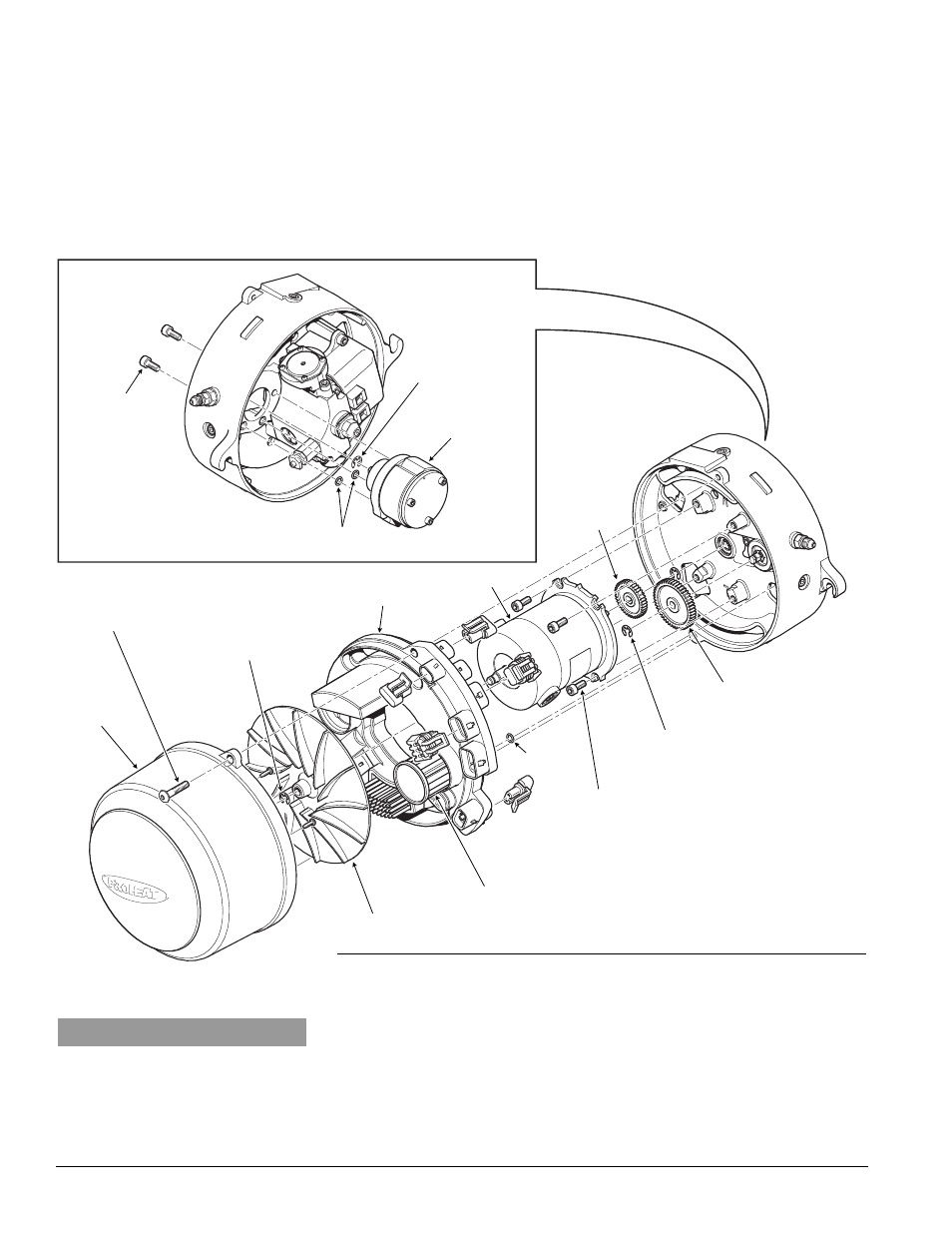
AIR COMPRESSOR
SCREWS
TORQUE = SEE
SECTION 1.3
O-RING
AIR
COMPRESSOR
GEAR LOCATING
SNAP RING
PROHEAT G-I PCM SERVICE MANUAL
4-16
i)
Reinstall gear locating snap ring, gear and gear retaining ring.
j)
Reinstall the Motor, with drive gear, take care to ensure that the Fuel
Pump seal is not damaged.
k)
Reinstall the G-I PCM, blower, blower retaining snap ring, Air Compressor
filter and blower housing.
l)
Reconnect the Motor, Fuel Shut-off Valve and Ignition Module connectors
at the G-I PCM.
m) Check air pressure. Adjust if necessary to correct pressure setting.
Go to page 4-12.
Figure 4-18: Air Compressor Replacement
BLOWER
HOUSING
BLOWER
RETAINING
SNAP RING
BLOWER
AIR COMPRESSOR FILTER
O-RING
MOTOR
AIR COMPRESSOR GEAR
DRIVE GEAR
G-I PCM
AIR COMPRESSOR GEAR
RETAINING RING
HOUSING SCREWS
TORQUE = SEE
SECTION 1.3
MOTOR SCREWS
TORQUE = SEE SECTION 1.3
NOTICE
All plugs/harnesses must be rein-
stalled into the Proheat Control
Module (G-I PCM) before heater goes
back into service.
n)
Reinstall the flame shield and ignition electrode assembly to the G-I PCM.
o)
Reinstall the burner head by mounting it against the heat exchanger face,
turning clockwise to engage the mounting ears on the bolts.
p)
Reinstall electrical harnesses and fuel supply line.
q)
Switch the PROHEAT on and operate for at least one complete cycle.
Observe the operation.
If a Start diagnostic code is indicated, proceed to Step 7.