For dmx512 systems, 24 bad boy, Spot luminaire user manual – PRG Bad Boy User Manual 1.6 User Manual
Page 32
24
BAD BOY
®
SPOT LUMINAIRE USER MANUAL
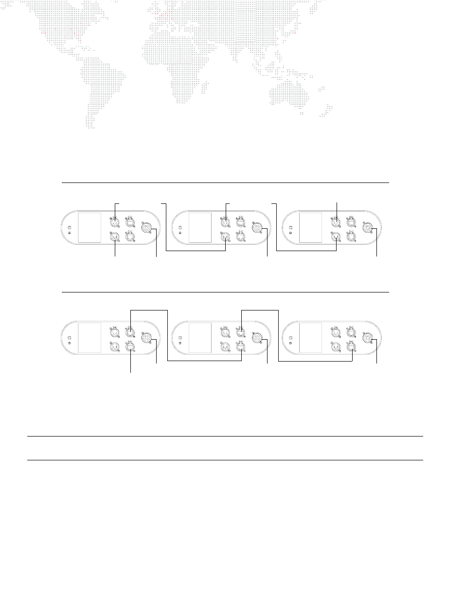
To connect power and data:
Step
1. Connect data cable (DMX512 or Ethernet) from console to appropriate input connector at first luminaire in
chain (Figure 2-10).
Step
2. If required, connect additional data cables from appropriate thru connectors to input connectors of
remaining luminaires in chain.
Step
3.
For DMX512 systems
: At last luminaire in chain, install male termination connector at DMX512 THRU
connector. (Luminaires and other devices on the same DMX512 chain may not function properly without
termination.) Refer to
"DMX512 Male Termination Connector"
Step
4. At each luminaire, connect AC Line Cord Cable Assembly from power input source.
Step
5. Dress and secure all cables so that they will not interfere with luminaire head or yoke movement.
*The Ethernet ports are not assigned as either In or Thru as the DMX512 ports are. Ethernet can be connected in any configuration.
Figure 2-10: Connecting Power and Data Cables
Note: If control data is active on both XLR and Ethernet connections, the fixture will follow the DMX512 commands
coming from the XLR.
200-240 VAC
15AMax
50 / 60 Hz
COMM
IN
DMX
THRU
ETHERNET
ACIN
200 -240VAC
15AMax
50/ 60Hz
COMM
IN
DMX
THRU
ETHERNET
ACIN
200 -240 VAC
15AMax
50/ 60 Hz
COMM
IN
DMX
THRU
ETHERNET
ACIN
DMX512 In
Power In
Power In
Power In
Termination
Connector
DMX512 Daisy-Chain
DMX512 Thru
DMX512 Thru
200-240 VAC
15AMax
50 / 60 Hz
COMM
IN
DMX
THRU
ETHERNET
ACIN
200 -240VAC
15AMax
50/ 60Hz
COMM
IN
DMX
THRU
ETHERNET
ACIN
200 -240 VAC
15AMax
50/ 60 Hz
COMM
IN
DMX
THRU
ETHERNET
ACIN
Ethernet
Power In
Ethernet Daisy-Chain *
Power In
Power In
Ethernet
Ethernet