2 addressing modes, 1 source immediate – Cypress enCoRe CY7C63310 User Manual
Page 9
CY7C63310, CY7C638xx
Document 38-08035 Rev. *K
Page 9 of 83
7.2 Addressing Modes
7.2.1 Source Immediate
The result of an instruction using this addressing mode is placed
in the A register, the F register, the SP register, or the X register,
which is specified as part of the instruction opcode. Operand 1
is an immediate value that serves as a source for the instruction.
Arithmetic instructions require two sources; the second source is
the A or the X register specified in the opcode. Instructions using
this addressing mode are two bytes in length.
Examples
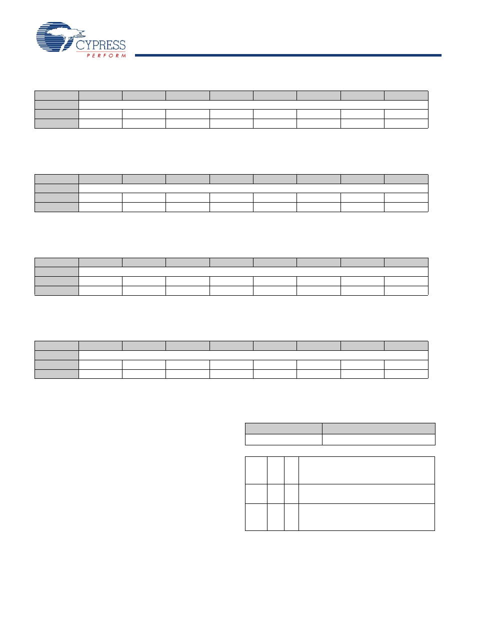
Table 7-3. CPU X Register (CPU_X)
Bit #
7
6
5
4
3
2
1
0
Field
X [7:0]
Read/Write
–
–
–
–
–
–
–
–
Default
0
0
0
0
0
0
0
0
Bit [7:0]:
X [7:0]
8-bit data value holds an index for any instruction that uses an indexed addressing mode.
Table 7-4. CPU Stack Pointer Register (CPU_SP)
Bit #
7
6
5
4
3
2
1
0
Field
Stack Pointer [7:0]
Read/Write
–
–
–
–
–
–
–
–
Default
0
0
0
0
0
0
0
0
Bit [7:0]:
Stack Pointer [7:0]
8-bit data value holds a pointer to the current top of the stack.
Table 7-5. CPU Program Counter High Register (CPU_PCH)
Bit #
7
6
5
4
3
2
1
0
Field
Program Counter [15:8]
Read/Write
–
–
–
–
–
–
–
–
Default
0
0
0
0
0
0
0
0
Bit [7:0]:
Program Counter [15:8]
8-bit data value holds the higher byte of the program counter.
Table 7-6. CPU Program Counter Low Register (CPU_PCL)
Bit #
7
6
5
4
3
2
1
0
Field
Program Counter [7:0]
Read/Write
–
–
–
–
–
–
–
–
Default
0
0
0
0
0
0
0
0
Bit [7:0]:
Program Counter [7:0]
8-bit data value holds the lower byte of the program counter.
Table 7-7. Source Immediate
Opcode
Operand 1
Instruction
Immediate Value
ADD
A
7
The immediate value of 7 is added with the
Accumulator and the result is placed in the
Accumulator.
MOV
X
8
The immediate value of 8 is moved to the X
register.
AND
F
9
The immediate value of 9 is logically ANDed with
the F register and the result is placed in the F
register.