1 i2c write operations, 2 i2c read operations, C write operations – Maxim Integrated 73S12xxF User Manual
Page 9: C read operations, Figure 8: device address, Figure 9: i, C write operation, Figure 10: i, C read operation, E bit
UG_12xxF_018
Using Synchronous Smart Cards with the 73S12xxF
Rev. 1.0
9
I/O
CLK
A16
0
R/
W
ACK
A15
D0
A14
D1
A13
D2
. . .
. . .
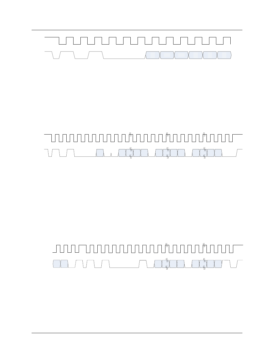
Figure 8: Device Address
2.3.1 I
2
C Write Operations
Write operations are formatted with the device address as the first byte. Bit 1 of the device address
contains the MSB of the memory address. This is bit A16 so the memory configuration of this card is
131Kb. The second byte contains address bits A15 to A8 and the third byte contains the address bits A7
to A0. The fourth byte will contain the data to write to the address specified in the command. If a single
byte is to be written, then a stop bit will follow the ACK bit. If more than one byte is to be written to
successive memory locations, then the data is written in successive bytes of the command until the last
one is written and then a stop bit follows it.
shows an I
2
Cwrite transaction. As with all memory
type cards, write operations must allow some time for the write operation to complete.
I/O
CLK
A1
6
A1
5
A1
4
A9
A8
A7
A6
A1
A0
AC
K
AC
K
Dn
Dn
-1
D1
D0
AC
K
AC
K
STOP
WRI
T
E
Figure 9: I
2
C Write Operation
2.3.2 I
2
C Read Operations
Read operations are a bit more complex. Read operations can start at the current address from a
previous transaction or the address can be specified in the current command. When the address is
specified in the current transaction, a dummy write sequence is required and then a read sequence is
executed. A dummy write will look identical to the sequence specified in
up to the ACK bit after
the LSB of the address is transferred.
shows the I
2
C read operation resuming from the last two
bits of the dummy write. A single byte can be read followed by a negative ACK (NACK) and a stop bit. If
more than one byte is to be read, then all received bytes will respond with an ACK until the last byte
which is then followed by a NACK. This protocol allows the reader to determine when the last byte is to
be received.
A1
A0
Dm
Dm-1
D1
D0
AC
K
NA
C
K
ST
O
P
. . .
. . .
I/O
CLK
AC
K
RE
A
D
Dn
Dm
+2
Dm+1
AC
K
Dn-1
ST
A
R
T
Figure 10: I
2
C Read Operation