3 reading data from the card, Figure 15: start bit and waitto, Figure 16: atr interrupt timing – Maxim Integrated 73S12xxF User Manual
Page 13
UG_12xxF_018
Using Synchronous Smart Cards with the 73S12xxF
Rev. 1.0
13
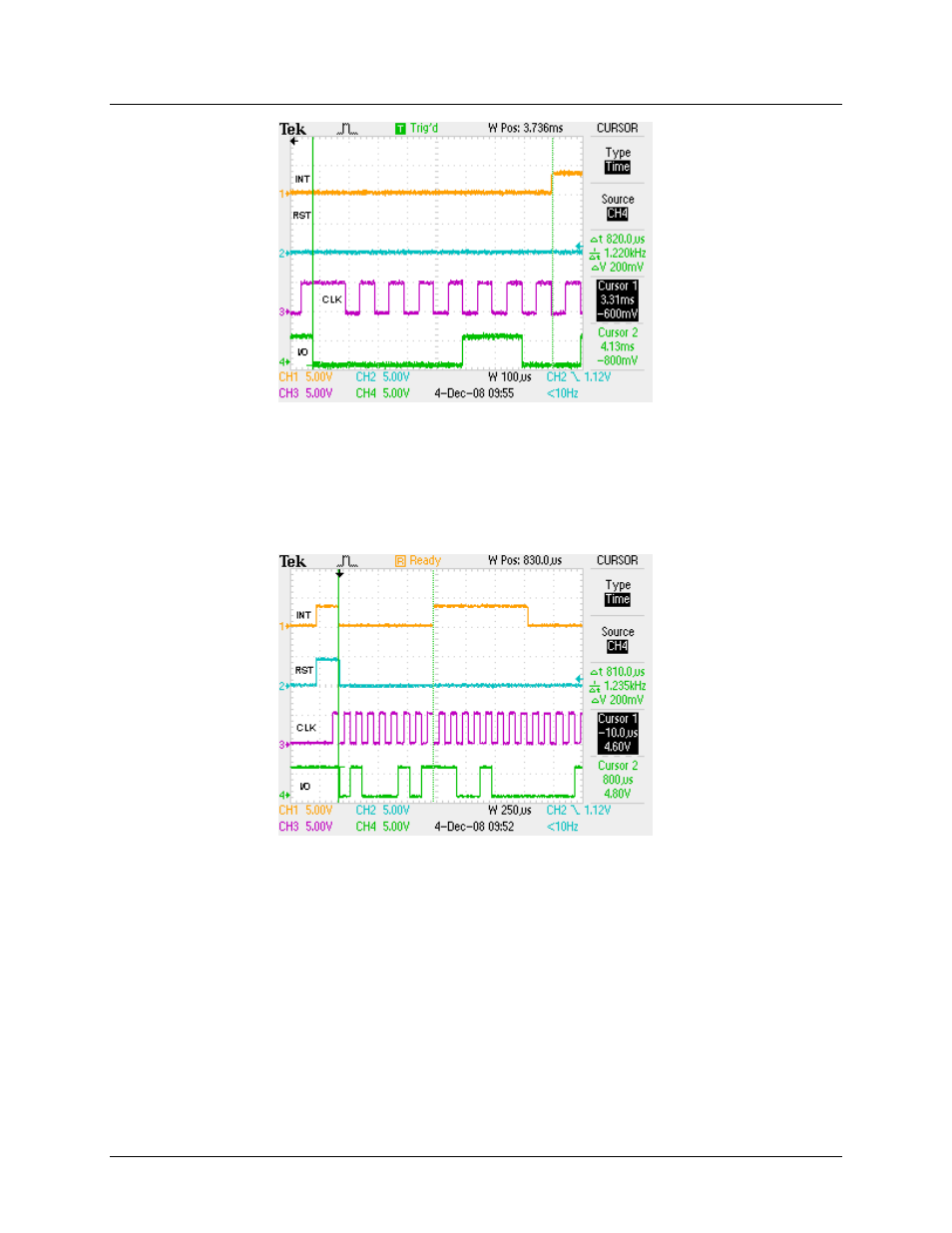
Figure 15: Start Bit and WAITTO
When reading the ATR response, setting RLEN to 9 on the last byte is not necessary, because RLEN is
set to 1 to generate the card reset and then RLEN is loaded with 8 for the four bytes of the ATR. This
sequence inherently provides the extra clock for the card reset. This is shown in
. The left
cursor shows where the WAITTO is generated for RLEN = 1 and the right cursor shows where the
interrupt is generated for RLEN = 8.
Figure 16: ATR Interrupt Timing
shows the send command flowchart.
3.2.1.3 Reading Data from the Card
When data is to be read from the card, the data must be clocked in after the stop bit. The first byte of the
data being read must set the RLEN counter at 9. Since the CLK was stopped high after the stop bit, the
first falling edge on CLK will configure the RX FIFO. The RLEN counter is now at 8 and the data byte is
ready to be read into the RX FIFO. The subsequent bytes can set the RLEN at 8 during the ISR. After
the last byte is received, the CLK should be stopped high to prepare for the next start bit at the beginning
of the next command frame. The read data flowchart is shown in
.