2 synchronous smart card basics, 1 2-wire cards, 1 answer to reset – Maxim Integrated 73S12xxF User Manual
Page 6: Synchronous smart card basics, Wire cards, Answer to reset, Figure 1: atr sequence
Using Synchronous Smart Cards with the 73S12xxF
UG_12xxF_018
6
Rev. 1.0
2 Synchronous Smart Card Basics
Most smart cards are the asynchronous type that operates similar to a standard serial UART for data
transfer. Async cards contain a microcontroller and a real time operating system (RTOS) to provide all the
functionality of the smart card according to the ISO-7816 specification.
Sync cards are typically thought of as memory cards that do not require the microcontroller functionality of
Async cards. The sync card only needs to read and write from the card’s memory and, for some cards,
provide simple security functions.
The async smart card interface requires a clock line (CLK) signal. This clock is not used to clock the data
transfers, but is supplied as a common timebase for the serial transfer logic and the microcontroller clock
source. Sync cards, as implied, use the CLK signal to clock the data one bit at a time for data transfers.
The 2-wire and 3-wire sync cards require the use of the Reset (RST) signal on the smart card interface to
control the reset function of the cards, and in the case of the 3-wire card, differentiate the card command
from the card output.
This document describes the format of the three types of cards based on the following:
2-wire card – SLE4432/SLE4442
3-wire card – SLE4418/SLE4428
I
2
C card – AT24C1024
Refer to the card data sheets for complete information.
2.1 2-Wire Cards
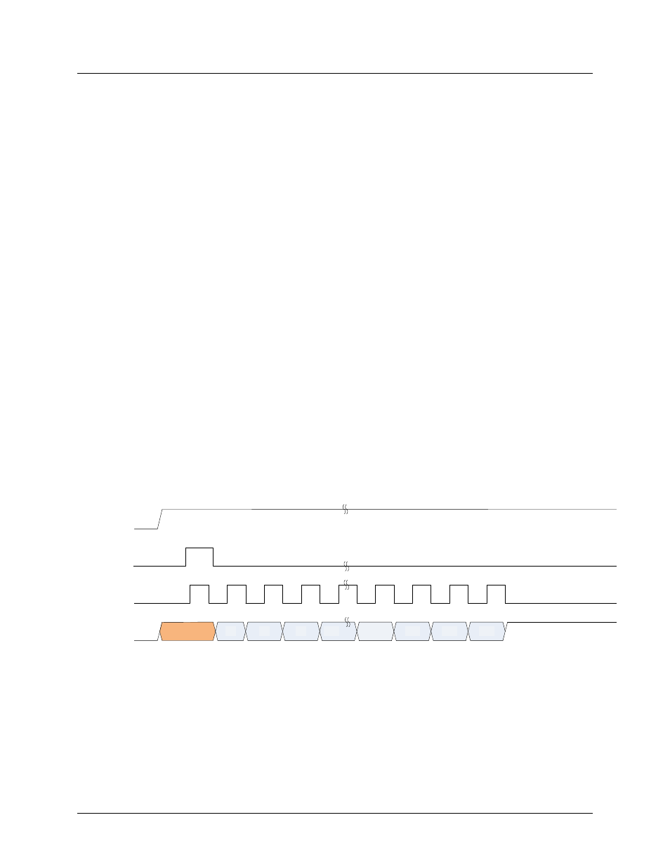
2.1.1 Answer to Reset
2-wire synchronous smart cards use the VCC, ground, I/O and RST smart card interface signals. A card
session begins with a card reset followed by an Answer To Reset (ATR). The ATR of a sync card is fixed
at 32 bits (4 bytes). The activation sequence is shown in
.
Vcc
RST
I/O
CLK
D1
D2
D3
D28
D29
D30
D31
D0
0
1
2
3
32
31
30
29
Figure 1: ATR Sequence
The session starts with turning on the power to the card (Vcc). Once the Vcc is stable, the RST signal is
asserted high and the CLK will output a single pulse. After the falling edge of CLK, the RST signal should
be de-asserted. The CLK should then be allowed to run for 32 cycles to capture all 32 bits of the ATR.
After the falling edge of the last clock pulse, the card will release the I/O line.