Figure 13: start bit zoom, Figure 14: stop bit zoom, Figure 13 – Maxim Integrated 73S12xxF User Manual
Page 12: A zoom of the st, Figure 14
Using Synchronous Smart Cards with the 73S12xxF
UG_12xxF_018
12
Rev. 1.0
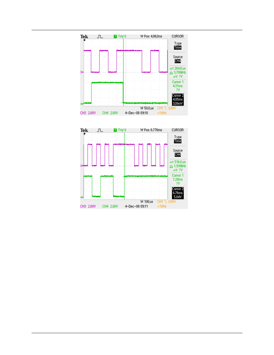
Figure 13: Start Bit Zoom
Figure 14: Stop Bit Zoom
The last byte of the command must load the RLEN register with a value of 9 to insure the last bit is
clocked properly. This is necessary because the first edge on CLK (after it is started) is falling. The next
rising edge will clock in the first bit of data. Since RLEN was loaded with 8, the interrupt will occur on the
8
th
falling edge. The WAITTO (CLK counter = RLEN) ISR will load the address byte to the TX FIFO, but it
won’t be placed on the I/O line until the next falling edge on CLK. The last bit of the command byte is
placed on the I/O line when the interrupt is generated and is clocked on the rising edge of CLK. Figure 15
shows the start bit (left cursor) and the command byte of a command frame. The right cursor shows
when the WAITTO is generated. The next rising edge on CLK is actually clocking the MSB of the
command byte. In order not to miss clocking the last bit of the data byte, the last byte of a command
frame must have RLEN set to 9.