2 command and response processing, 2 3-wire cards, 1 answer to reset – Maxim Integrated 73S12xxF User Manual
Page 7: Command and response processing, Wire cards, Answer to reset, Figure 2: command packet format, Figure 3: read command operation, Figure 4: write and security command operation
UG_12xxF_018
Using Synchronous Smart Cards with the 73S12xxF
Rev. 1.0
7
2.1.2 Command and Response Processing
After the ATR response has been processed, the card is now ready to accept a command. Commands
are three bytes in length and are formatted as shown in Figure 2.
Byte 1
Byte
2
Byte
3
Command
Address
Data
Figure 2: Command Packet Format
Each byte is transmitted with least significant bit first. The command byte is sent first and specifies the
type of command to be executed. This consists of read, write and security commands. The second byte
specifies the 8-bit address for the command to operate upon. Since the address is limited to 8-bits, the
size of the memory is 256-bytes max. The last byte corresponds to a single byte of data. Write
operations are limited to single bytes writes. Read operations ignore the data field and are considered
don’t care.
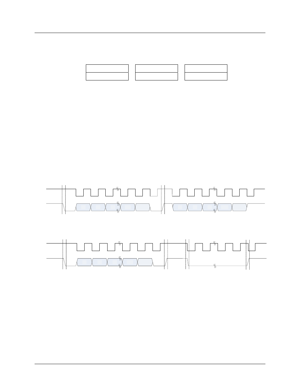
Each command begins with a start bit. The start bit is defined as a falling edge on I/O while the CLK is
high. The command is transferred on 24 clocks and then followed by a stop bit. Every command expects
data (in case of a read operation) or an indication that it is processing the command (in the case of a write
or security operation).
shows the command read operation and
shows the write and
security command operations. Since these types of cards were based on an old flash based technology,
they required a long write time. To prevent any commands from being executed while the previous one is
being processed, the status can be monitored as shown in
or a delay can be executed to allow
for the processing to complete.
C1
C2
C22
C23
D0
D1
D2
1
2
3
24
C0
I/O
CLK
23
START
0
1
2
3
0
Dn-1
Dn
n
STOP
Figure 3: Read Command Operation
C1
C2
C22
C23
1
2
3
24
C0
I/O
CLK
23
START
0
1
2
0
STOP
Processing
Start
Processing
Stop
Figure 4: Write and Security Command Operation
The RST signal is not used for normal transactions, but can be used as a break signal by applying a
positive pulse on RST for a minimum duration.
2.2 3-Wire Cards
2.2.1 Answer to Reset
The ATR sequence is identical to the 2-wire cards as outlined in