2 3-wire card operation, 1 atr retrieval, 2 sending commands – Maxim Integrated 73S12xxF User Manual
Page 14: Wire card operation, Figure 17: 3-wire command frame
Using Synchronous Smart Cards with the 73S12xxF
UG_12xxF_018
14
Rev. 1.0
3.2.2 3-Wire Card Operation
3.2.2.1 ATR Retrieval
The ATR retrieval for 3-wire cards is exactly the same as for 2-wire cards. See
3.2.2.2 Sending Commands
3-wire card commands must follow the format as described in
. Instead of using the start
and stop bits as 2-wire cards, the 3-wire cards surround the command frame with the RST output set
high. 3-wire card command frames are tricky with the 73S12xxF smart card logic as they expect the CLK
to be stopped low and then start CLK so the first edge output is a rising edge. As explained previously,
the transmit and receive FIFOs require a falling edge on CLK to be configured before a rising edge will
clock the data properly. To work around this, the CLK should be high before starting the command frame.
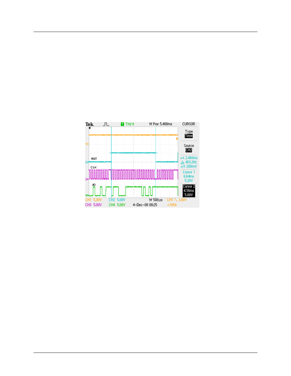
In this way, the CLK will start with a falling edge so the FIFOs are ready. A scope capture of the
command frame is shown in Figure 17.
Figure 17: 3-Wire Command Frame
The proper timing of the 3-wire card has the CLK low when the RST is taken high. Unfortunately, to
ensure the first edge output on CLK is a falling one, the RST can’t be taken high while CLK is high. To
work around this, the CLK must be started and be allowed to go low before taking RST high to start the
command frame. By setting RLEN at 1 before starting CLK, the first falling edge of CLK will generate an
interrupt and the ISR can then set RST high. The ISR should then set RLEN to 7 and continue. The
WAITTO interrupt timing is shown in
. The Left cursor shown the interrupt when RLEN = 1 and
the right cursor shows the interrupt when RLEN = 7.
shows a zoom in of the CLK falling edge
and the RST being set soon after by the ISR. When the WAITTO interrupt occurs, the command byte has
been sent and the address byte should be written to the TX FIFO. From this point on, the RLEN
configuration is identical to the 2-wire cards, where the address byte is sent to the TX FIFO with RLEN set
at 8 and the data byte (last byte of the command frame) is sent with RLEN set to 9.