Figure 23: i, C data read, Figure 24 : i – Maxim Integrated 73S12xxF User Manual
Page 18: C read operation termination, To be written, Figure 23
Using Synchronous Smart Cards with the 73S12xxF
UG_12xxF_018
18
Rev. 1.0
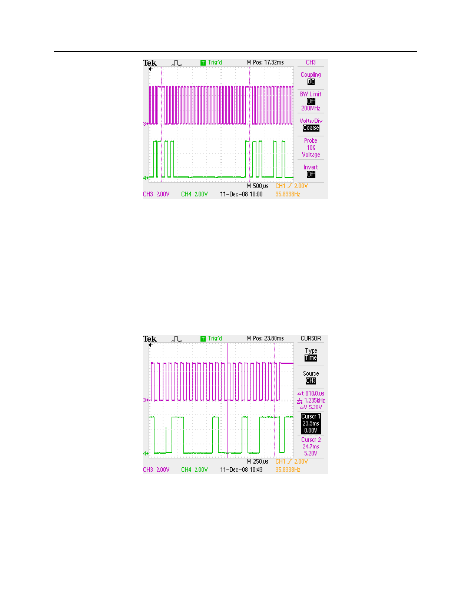
Figure 23: I
2
C Data Read
The read operations can read continuous consecutive memory locations as long as the ACK from the
reader is low. The IO and IOD bits need to be set low after this ACK bit completes (device address with
R/W set high). This configures the ACK bit to output a logic zero for the next byte read after the WAITTO
interrupt is generated. The ISR will read the byte and set the RLEN to 9 to read the next byte. To signal
the card that the reader wants to stop reading, the last ACK must be set high. During the ISR, if the next
byte is to be the last one read, the IOD bit must be set for output and the I/O bit must be set high to
generate the NAK after the previous ACK bit time is complete. After the next WAITTO interrupt, the ACK
bit will output a logic one (NAK) to signal the card that the read operation is complete. The CLK should
be stopped high with the IOD and I/O bits set low after the NAK bit time completes to prepare the stop bit.
The I/O bit should then be set high to output the stop bit. The read operation is now complete.
shows an example of the end of a read operation. The left cursor marks the next to last ACK bit and the
right cursor shows the last NAK bit. The stop bit is shown after the NAK bit.
Figure 24 : I
2
C Read Operation Termination