Installation (cont.), Backwash flow control replacement, Plumbing connections – Culligan Platinum Plus Series User Manual
Page 18: Bypass valve installation
14
Installation
(cont.)
Backwash Flow Control Replacement:
• Remove the drain clip and pull the drain elbow straight off.
• Remove the backwash flow control located behind the elbow.
• Install the correct backwash flow control.
• Reverse the procedure to reassemble.
Plumbing Connections
Shipped with each softener is a Culligan
®
bypass valve, which is used to connect the softener to
the plumbing system. The bypass allows the softener to be isolated from the water service line if
service is necessary while still providing water to the home. See the parts list for connectors that
are available.
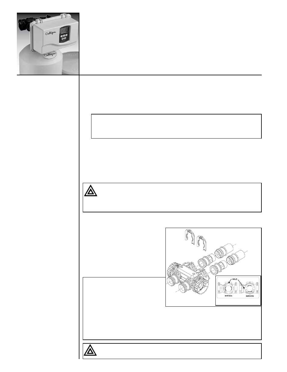
Bypass Valve Installation
The bypass valve connects directly to the
control valve with a pair of couplings and
two assembly pins. Lubricate all O-rings on
the couplings with silicone lubricant.
The bypass valve is in the service position
when the handle is rotated as far back as
possible (See figures 7a and 7b).
Caution! Close the inlet supply line and relieve system pressure before cutting into
the plumbing! Flooding could result if not done!
Caution! When making sweat connections, use care to keep heat away from the
plastic nuts used to connect the plumbing to the bypass. Damage to these components
may otherwise result.
Note: If the ground from the electrical
panel or breaker box to the water meter
or underground copper pipe is tied to
the copper water lines and these lines
are cut during installation of the bypass
valve, an approved grounding strap must
be used between the two lines that have
been cut in order to maintain continuity. The length of the grounding strap will depend upon
the number of units being installed. In all cases where metal pipe was originally used and is
later interrupted by the bypass valve to maintain proper metallic pipe bonding, an approved
ground clamp c/w not less than #6 copper conductor must be used for continuity. Check your
local electrical code for the correct clamp and cable size.
Caution! To bypass the valve, turn bypass knob on both sides of the valve to bypass
position (see figure 7b). When returning to service, put the inlet into service before the
outlet.
Note: The number on the flow control should face into the valve body.
Note: Dip switch #5 is to be in the “off ” position for 10” and 12” Tanks (0.25 gpm
refill flow control). Dip switch 5 is to be in the “on” position for 14” and 16” tanks (0.50
gpm brine refill flow control).
Figure 7a
Figure 7b