The tvn 20 – front panel 3, The tvn 20 – front panel – Interlogix NVR 20 User Manual User Manual
Page 9
TruVision NVR 20 User Manual
3
The TVN 20 – Front Panel
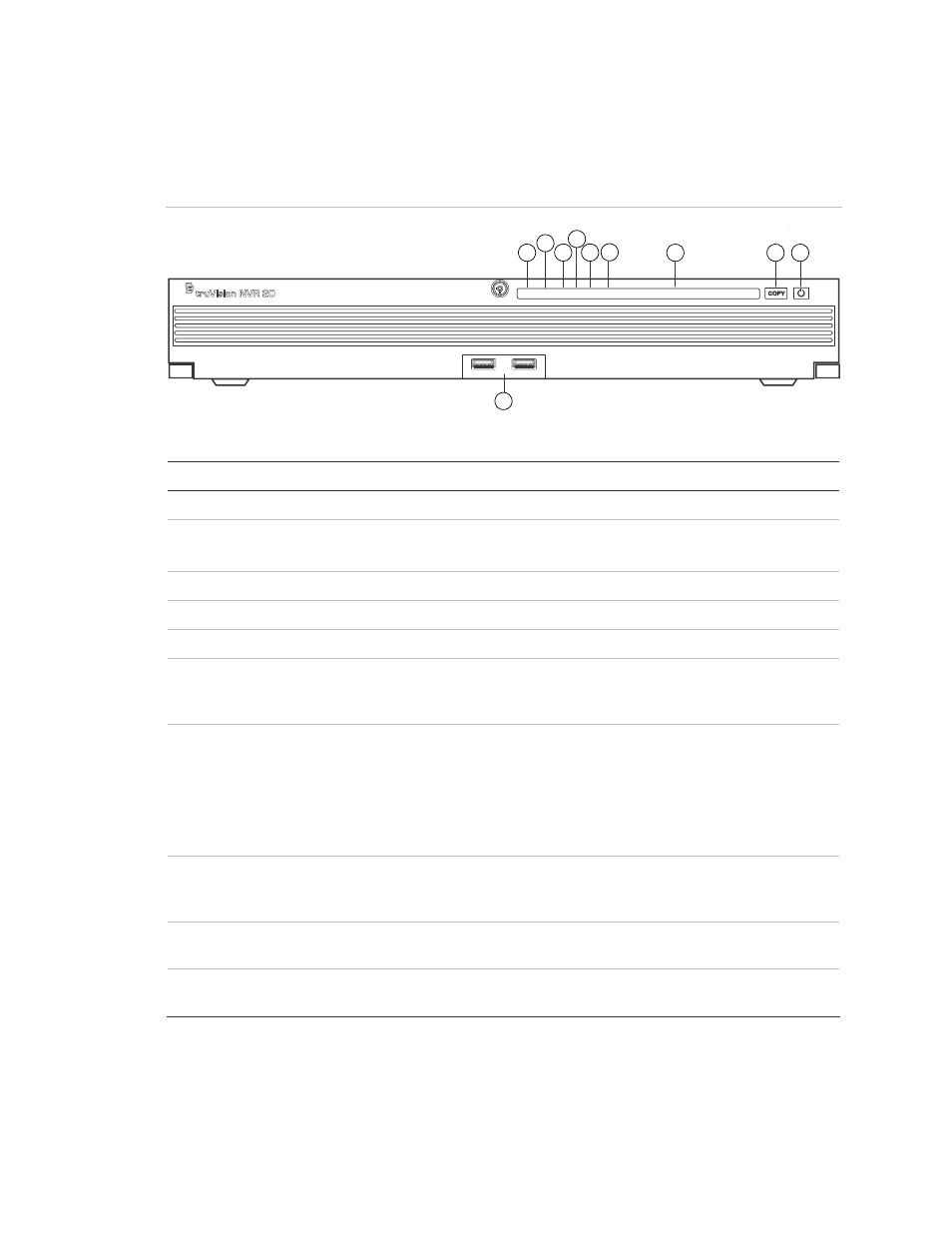
Figure 1: The TVN front panel
1 2 3 4 5 6 7 8 9 10 11 12 13 14 15 16
POWER ALARM TX/R/X HDD READY ARCHIVE
7
8
9
10
1
2
3
5
6
4
Table 1: Front Panel Elements
No Element
Description
LED Status Light
1
Power LED
Shows that unit is powered
Color = Normal
2
Alarm LED
Shows if there are any alerts
RED = Fault
OFF = Normal
3
TX/RX LED
Shows unit is communicating across the network
Blue Flashing
4
HDD LED
Show read/write activity to the HDDs
Red Flashing
5
READY
Shows that the unit is full ready to function
Blue = Normal
6
ARCHIVE
Shows the status of the archive to USB operation. A
buzzer alarm will sound if an incompatible USB
device is detected.
Blue = Archiving
7
Channel LEDs
Shows the connected status of IP cameras to the
TVN 20, also provides indication of the record mode
of channel
View or Scheduled Record
(No Event) = Blue
Event + View (no record) =
Red
View or Event + Record =
Purple
8
COPY Button
When a USB Drive is connected to the USB Port on
the front of unit, pressing the COPY button initiates
archiving the most recent video to the USB drive
Archive LED glows BLUE
during operation
9
POWER Button Pressing this button for 3 seconds allows for a
controlled shutdown of the unit
N/A
10
USB 2.0 Ports
(2)
Used by the Copy button or via Remote Backup
managed through the Browser
N/A