Interlogix NVR 20 User Manual User Manual
Page 130
124
TruVision NVR 20 User Manual
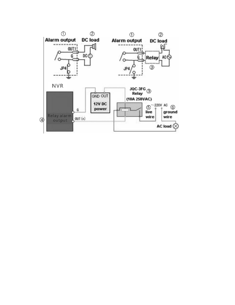
To connect to an AC/DC load, use the following diagram:
1. Alarm
output
2. DC
load
3. Relay
4. Relay
alarm
output
5. Live
wire
6. Ground
wire
For a DC load, JP4 can be used within the limit of 12V/1A safely. If the interface
is connected to an AC load, JP4 should be left open. Use an external relay for
safety (as shown in the figure above).
Note:
An external relay is needed to prevent electric shock when connecting to
an AC load.
Alarm Connections:
The device provides the green mating plugs for alarm input and alarm output
connectors. Perform the following steps for proper connection:
1. Remove the green mating plug from the ALARM IN or ALARM OUT
connector.
2. Use a screwdriver to loosen the screw in the plug and then place the wire to
the top of screw and finally tighten the screw to secure the wires.
3. Insert the plug to its mating slot.