Balance the model (c.g.) – Great Planes Edge 540 1.60-43cc Performance Series ARF - GPMA1414 User Manual
Page 45
45
These are the recommended control surface throws:
HIGH RATE
ELEVATOR:
2" [51mm], 22° up
2" [51mm], 22° down
RUDDER:
4-1/2" [114mm], 27° left
4-1/2" [114mm], 27° right
AILERONS:
3/4" [19mm], 12° up
3/4" [19mm], 12° down
LOW RATE
ELEVATOR:
1-1/2" [38mm], 17° up
1-1/2" [38mm], 17° down
RUDDER:
3" [76mm], 18° left
3" [76mm], 18° right
AILERONS:
1/2" [13mm], 8° up
1/2" [13mm], 8° down
3D RATE
ELEVATOR:
2-3/4" [70mm], 32° up
2-3/4" [70mm], 32° down
RUDDER:
5-1/2" [140mm], 34° left
5-1/2" [140mm], 34° right
AILERONS:
1-7/8" [48mm], 32° up
1-7/8" [48mm], 32° down
NOTE: The throws are measured at the widest part of
the control surfaces.
IMPORTANT: The Edge 540 1.60 ARF has been
extensively flown and tested to arrive at the throws at
which it flies best. Flying your model at these throws
will provide you with the greatest chance for successful
first flights. If, after you have become accustomed to the
way the Edge 540 flies, you would like to change the
throws to suit your taste, that is fine. However, too much
control throw could make the model difficult to control, so
remember, “more is not always better.”
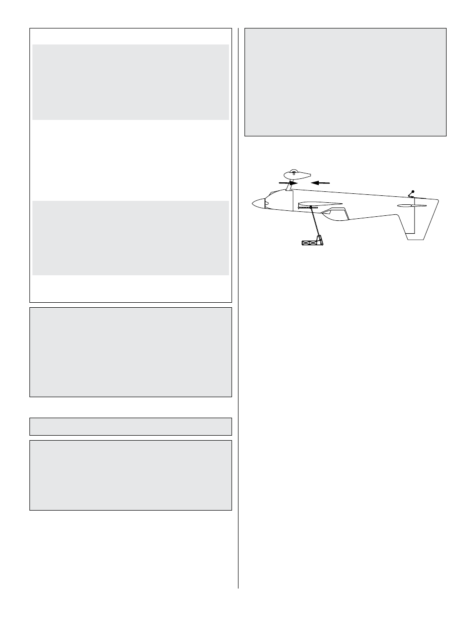
Balance the Model (C.g.)
More than any other factor, the
C.G. (balance point)
can have the
greatest effect on how a model flies, and
may determine whether or not your first flight will be
successful. If you value this model and wish to enjoy it for
many flights,
DO NOT OVERLOOK THIS IMPORTANT
PROCEDURE. A model that is not properly balanced will
be unstable and possibly unflyable.
At this stage the model should be in ready-to-fly condition
with all of the systems in place including the engine, landing
gear, covering and paint, and the radio system.
o
1. Use a felt-tip pen or 1/8" [3mm]-wide tape to accurately
mark the C.G. on the top of the wing on both sides of the
fuselage. The C.G. is located 4-5/16" [110mm] back from the
leading edge of the wing.
This is where your model should balance for the first
flights. Later, you may wish to experiment by shifting
the C.G. up to 1/2" [13mm] forward or 1/2" [13mm] back
to change the flying characteristics. Moving the C.G.
forward may improve the smoothness and stability, but
the model may then require more speed for takeoff and
make it more difficult to slow for landing. Moving the C.G.
aft makes the model more maneuverable, but could also
cause it to become too difficult to control. In any case,
start at the recommended balance point and do not at
any time balance the model outside the specified range.
4-5/16" [110mm]
o
2. With the wing attached to the fuselage, all parts of the
model installed (ready to fly) and an empty fuel tank, place
the model upside-down on a Great Planes CG Machine, or
lift it at the balance point you marked. If you are using a
brushless motor, be sure to balance the airplane with the
battery pack installed.
o
3. If the tail drops, the model is “tail heavy” and the receiver
battery pack and/or receiver must be shifted forward or weight
must be added to the nose to balance (also see rudder servo
installation section). If the nose drops, the model is “nose
heavy” and the receiver battery pack and/or receiver must be
shifted aft or weight must be added to the tail to balance (also
see rudder servo installation section). If possible, relocate
the battery pack and receiver to minimize or eliminate any
additional ballast required. If additional weight is required,
use Great Planes (GPMQ4485) “stick on” lead. A good place
to add stick-on nose weight is to the motor mounting box
(don’t attach weight to the cowl—it is not intended to support
weight). Begin by placing incrementally increasing amounts
of weight on the bottom of the fuse over the firewall until the
model balances. Once you have determined the amount of
weight required, it can be permanently attached. If required,
tail weight may be added by cutting open the bottom of the
fuse and gluing it permanently inside.
Note: Do not rely upon the adhesive on the back of the lead
weight to permanently hold it in place. Over time, fuel and
exhaust residue may soften the adhesive and cause the
weight to fall off. Use #2 sheet metal screws, RTV silicone,
or epoxy to permanently hold the weight in place.
o
4.
IMPORTANT: If you found it necessary to add any weight,
recheck the C.G. after the weight has been installed.