Install the rudder servos, Install the rudder servos in the forward position – Great Planes Edge 540 1.60-43cc Performance Series ARF - GPMA1414 User Manual
Page 33
33
INSTALL ThE RUDDER SERVOS
These two sections refer to installing the rudder servos
in the forward position utilizing a pull-pull system and
installing them in the aft position utilizing pushrods. If you
have not yet decided which installation is necessary for
your power system, consider the following for each type:
gLOw ENgINE
The weight of the O.S. 1.60 FX and Pitts muffler (39 oz
[1106 g]) require that the rudder servos be installed in the
forward position utilizing a pull-pull rudder system to balance
the airplane at the recommended C.G. with the addition of
extra ballast at the nose of the plane. If you are installing an
engine that is heavier than the 1.60 FX, you may wish to
check the current C.G. of the plane before proceeding.
gAS ENgINE
Most gas engine installations (including the Fuji-Imvac 43
EI-2 engine) will require the rudder servos to be installed
in the aft position. We suggest checking the balance
before you proceed with the rudder servo installation if
you are installing a lighter engine. The Fuji-Imvac BT-43
EI-2 engine weighs 64 oz [1814 g] with the muffler, EI
unit, prop bolt, and prop washer (also consider the weight
of the ignition battery pack you will be using).
BRUShLESS MOTOR
Battery size and voltage will ultimately determine the
optimum rudder servo position. We suggest checking the
balance of the airplane at this time before proceeding
with the rudder servo installation.
ChECk ThE CURRENT BALANCE OF ThE MODEL
Check the balance of the model by installing the wing
onto the fuse, sliding the cowl over the firewall and taping
it in place (it is okay if the cowl is not on the fuselage
straight), and installing your propeller and spinner. These
components only need to be loosely installed and are only
for checking balance of the plane. Follow the balancing
procedure described on page 45 of this manual. With the
C.G. set at the recommended distance, experiment with
the rudder servos by placing them both into the forward
rudder servo tray, as well as resting them on the tail of the
plane near the leading edge of the stabilizer. The receiver
battery pack should also be placed either onto the radio
tray (refer to “Install the Radio System” on page 43), or
the motor mouning box.
Install the Rudder Servos in the
Forward position
RECOMMENDED INSTALLATION FOR gLOw ENgINES
o
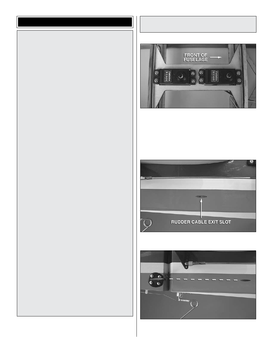
1. Position the rudder servos into the servo tray as shown.
Drill a 1/16" [1.6 mm] hole through the mounting holes of
each servo. Install and remove a mounting screw from each
hole and apply a couple drops of thin CA into the holes to
harden the wood. After the glue has hardened, install the
servos into the openings with the servo splines towards the
front of the plane using the hardware that came with your
servos. Center the servos with your radio system.
o
2. Trim the covering from the rudder cable exit slots that
are located beneath the horizontal stabilizer.
o
3. Locate the plywood mounting plates beneath the
covering on both sides of the rudder. Place a control horn on
each side of the rudder, positioning them as shown, aligning