Install the throttle servo (glow) – Great Planes Edge 540 1.60-43cc Performance Series ARF - GPMA1414 User Manual
Page 21
21
o
6. Insert the fuel tank into the fuselage as shown with
the neck of the tank pushed as far forward in the hole in the
fuselage as it will fit. The vent line should be at the top of the
tank. Secure the fuel tank inside the fuse by hooking two
of the included rubber bands around the rubber band tabs
as shown. Attach a length of fuel tubing approximately 9"
[229mm] long to each of the fuel tank tubes.
o
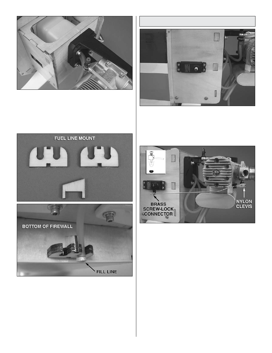
7. Cut the fuel tubing on the vent and carb lines to the
necessary length and connect them to the engine. Locate
the three pieces that make the optional
fuel line mount. This
part is used to hold the fill line at the bottom of the firewall (if
an Easy Fueler valve is being used or some similar system,
this part can be omitted). Glue the pieces together as shown.
Use epoxy to fuel proof the part. Sand the bottom center
of the firewall where the part will be glued with 220 grit
sandpaper. Glue the piece in place and clip the fill line into
one of the slots in the fuel line mount. The fill line can now be
cut to length. A fuel line plug is provided for the fill line.
Install the Throttle Servo (glow)
o
1. Attach the throttle servo to the firewall box as shown
using the hardware included with the servo. Be sure to use
thin CA in the servo mounting holes.
o
2. Cut three arms from a four arm servo arm and attach it
to the throttle servo pointing down.
o
3. Install a brass screw-lock pushrod connector using
a nylon retainer to the outer hole in the throttle servo arm.
Loosely install a 4-40 x 1/8" [3mm] SHCS into the brass
screw-lock connector. Install a nylon clevis and silicone clevis
retainer 20 complete turns onto the .074" x 12" [1.9mm x
305mm] pushrod and bend the pushrod to fit from the throttle
servo arm to the carburetor arm. When bending the rod, be
sure there is clearance between the engine/muffler and
the pushrod through the entire travel of the throttle servo.
Metal to metal contact will cause radio interference. When
satisfied, fit the pushrod through the screw-lock connector
and connect the clevis to the carburetor arm. Slide the
silicone clevis retainer to the end of the clevis and make
any necessary adjustments to the pushrod length. Use your
radio system to test the operation of the throttle servo. With
all fine adjustments made, finish tightening the 4-40 x 1/8"
[3mm] SHCS against the pushrod.