Check the control directions, Set the control throws – Great Planes Edge 540 1.60-43cc Performance Series ARF - GPMA1414 User Manual
Page 44
44
Different
voltages
PARALLEL
adapter
11.1V (3-Cell)
3200mAh
7.4V (2-Cell)
3200mAh
NO!!!
NEVER connect battery packs with different voltages
in parallel! Only combine them in series. Otherwise, the
batteries with lower voltage will try to “equalize” with the
batteries that have a higher voltage. Current will flow from
the higher voltage battery into the lower one, essentially
“charging” the lower voltage battery pack. This situation will
likely cause heat and possibly a fire.
Different
capacities
11.1V (3-Cell)
3200mAh
NO!!!
11.1V (3-Cell)
1250mAh
NEVER connect battery packs with different capacities in
series or in parallel.
LITHIUM BATTERY HANDLING AND USAGE
WARNING!! Read the entire instruction sheet included
with the battery. Failure to follow all instructions could cause
permanent damage to the battery and its surroundings,
and cause bodily harm!
• ONLY use a LiPo approved charger. NEVER use a
NiCd/NiMH peak charger!
• NEVER charge in excess of 4.20V per cell.
• ONLY charge through the “charge” lead. NEVER charge
through the “discharge” lead.
• NEVER charge at currents greater than 1C.
• ALWAYS set charger’s output volts to match battery volts.
• ALWAYS charge in a fireproof location.
• NEVER trickle charge.
• NEVER allow battery temperature to exceed 150°F (65°C).
• NEVER disassemble or modify pack wiring in any way
or puncture cells.
• NEVER discharge below 2.5V per cell.
• NEVER place on combustible materials or leave
unattended during charge or discharge.
• ALWAYS KEEP OUT OF REACH OF CHILDREN.
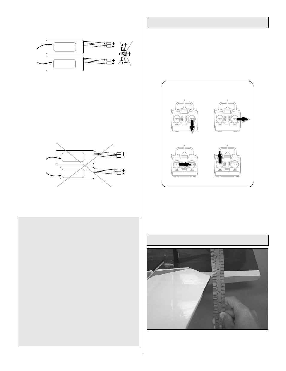
Check the Control Directions
o
1. Turn on the transmitter and receiver and center the
trims. If necessary, remove the servo arms from the servos
and reposition them so they are centered. Reinstall the
screws that hold on the servo arms.
o
2. With the transmitter and receiver still on, check all the
control surfaces to see if they are centered. If necessary, adjust
the clevises on the pushrods to center the control surfaces.
FULL THROTTLE
RUDDER MOVES RIGHT
ELEVATOR MOVES UP
RIGHT AILERON MOVES UP
LEFT AILERON MOVES DOWN
4-CHANNEL RADIO SETUP
(STANDARD MODE 2)
o
3. Make certain that the control surfaces and the carburetor
respond in the correct direction as shown in the diagram.
If any of the controls respond in the wrong direction, use
the servo reversing in the transmitter to reverse the servos
connected to those controls. Be certain the control surfaces
have remained centered. Adjust if necessary.
Set the Control Throws
Use a ruler to accurately measure and set the control throw
of each control surface as indicated in the chart that follows.
If your radio does not have dual rates, we recommend setting
the throws at the
low rate setting for your first few flights.