Get ready to build, Metric conversions common abbreviations, Balsa basswood plywood – Great Planes CAP 232 40 Kit - GPMA0232 User Manual
Page 5
5
There are two types of screws used in this kit:
Sheet metal screws are designated by a number and
a length.
For example #4 x 3/4"
Machine screws are designated by a number, threads per
inch and a length.
For example 4-40 x 3/4"
When you see the term “test fit” in the instructions, it
means you should first position the part on the assembly
without using any glue, then slightly modify the part as
necessary for the best fit.
Whenever just “epoxy” is specified you may use
either
30-minute epoxy
or 6-minute epoxy. When 30-minute epoxy
is specified it is highly recommended that you use only
30-minute (or slower) epoxy because you will need either
the working time and/or the additional strength.
Several times during construction we refer to the “top” or
“bottom” of the model or a part of the model. For example,
during wing construction we tell you to “glue the top main
spar” or “trim the bottom of the former.” It is understood that
the “top” or “bottom” of the model is as it would be when the
airplane is right side up and will be referred to as the “top”
even if the model is being worked on upside down,
i.e. the
“top” main spar is always the “top” main spar even when the
wing is being built upside down.
Elev = Elevator
Fuse = Fuselage
LE = Leading Edge (front)
LG = Landing Gear
Ply = Plywood
Stab = Stabilizer
TE = Trailing Edge (rear)
" = Inches
1. Unroll the plan sheets. Reroll the plans inside out to
make them lie flat.
2. Remove all parts from the box. As you do, determine the
name of each part by comparing it with the plan and the
parts list included with this kit. Using a felt-tip or ballpoint
pen, lightly write the part name or size on each piece to
avoid confusion later. Use the die-cut patterns shown on
pages 6 and 7 to identify the die-cut parts and mark them
before removing them from the sheet. Save all scraps. If
any of the die-cut parts are difficult to punch out, do not
force them! Instead, cut around the parts with a hobby
knife. After punching out the die-cut parts, use your bar
sander or sanding block to lightly sand the edges to
remove any die-cutting irregularities or slivers.
3. As you identify and mark the parts, separate them into
groups, such as fuse (fuselage), wing, fin, stab (stabilizer)
and hardware.
Zipper-top food storage bags are handy for storing your
par ts as you sor t, identify and separate them into
sub-assemblies.
Get Ready to Build
1/64" = .4mm
1/32" = .8mm
1/16" = 1.6mm
3/32" = 2.4mm
1/8" = 3.2mm
5/32" = 4mm
3/16" = 4.8mm
1/4" = 6.4mm
3/8" = 9.5mm
1/2" = 12.7mm
5/8" = 15.9mm
3/4" = 19mm
1" = 25.4mm
2" = 50.8mm
3" = 76.2mm
6" = 152.4mm
12" = 304.8mm
15" = 381mm
18" = 457.2mm
21" = 533.4mm
24" = 609.6mm
30" = 762mm
36" = 914.4mm
1" = 25.4mm (conversion factor)
Metric Conversions
Common Abbreviations
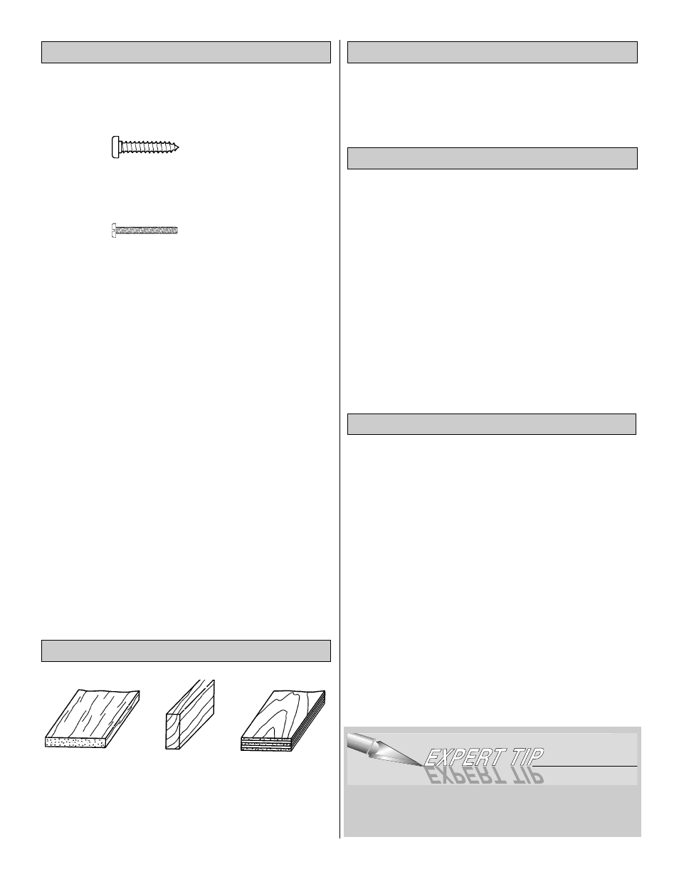
Balsa Basswood Plywood
Types of Wood
Building Notes