Great Planes CAP 232 40 Kit - GPMA0232 User Manual
Page 19
❏
3. Lay the other fuselage side next to the right side as
shown in the photo and label it on the inside as the LEFT.
It is important that you lay the fuselage sides in a mirrored
position to insure that you build a right and a left half.
❏
4. Use medium CA to accurately glue a fuselage
doubler to the inside of the right fuselage side. Make sure
the doubler aligns with the fuselage side where the arrows
indicate in the photo.
❏
5. Glue the left fuselage doubler to the left fuselage side
in the same manner.
❏
6. Drill a 3/16" hole through each of the punch marks in
formers F-3, F-5 and F-7
Hint: Place the formers on a scrap piece of wood and
press down as you drill the hole so the former does not
split when the drill goes through.
❏
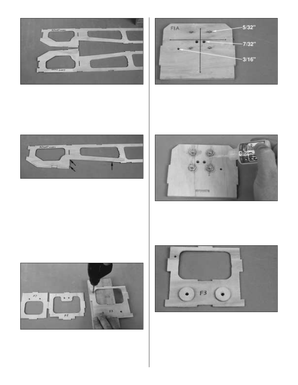
7. Draw center lines connecting the outer punch marks
on the firewall. Drill 5/32" holes for the engine mount bolts
at the four engine mount punch marks. Drill a 3/16" hole for
the throttle pushrod at the punch mark. Drill two 7/32" holes
for the fuel line.
❏
8. Press four supplied 6-32 blind nuts into the holes on
the back of the engine mount. Gently tap the blind nuts with
a hammer to fully seat them into the firewall. Add a few
drops of thin CA around the blind nuts to secure them.
❏
9. Align the F-3 doublers over the die-cut holes in F-3,
and glue them in place using medium CA.
19