Attach the canopy install the hardware – Great Planes CAP 232 40 Kit - GPMA0232 User Manual
Page 39
❏
5. Remove the pin and add 6 drops of thin CA to the
center of all the hinges on both the top and the bottom.
Do not use accelerator on any of the hinges. Do not glue
the hinges with anything but thin CA and do not attempt
to glue one half of the hinge at a time with medium or
thick CA. They will not be properly secured and the
controls could separate while the model is in flight.
❏
6. Join the rudder to the fin with the hinges and use
30-minute epoxy to simultaneously glue the tail gear wire in
the rudder and the tail gear bearing in the fuse. Do not
glue the nylon bearing to the rudder. Glue the hinges in
position with thin CA.
Hint: Applying a little petroleum jelly to the tail gear wire
where it passes through the nylon bearing will prevent the
wire from being glued into the bearing.
❏
7. Prepare the hinge slots in the ailerons the same way
you did for the tail surfaces.
❏
8. Use a toothpick to pack the torque rod holes in the
ailerons with 30-minute epoxy, then join the ailerons to the
wing with the hinges. Glue the hinges with thin CA. Wipe
away the epoxy that is squeezed out of the ailerons with a
paper towel and alcohol.
❏
1. Install a 1" tail wheel with two 3/32" wheel collars.
❏
2. Install the wheels in the wheel pants (don't forget the
masking tape so the screw doesn't scratch the paint), then
mount the wheel pants to the landing gear. Secure the 8-32
nuts with a drop of thread lock.
❏
3. Mount the landing gear to the fuselage with the
8-32 x 3/4" socket head cap screws and #8 washers.
❏
4. Install the elevator, rudder and throttle pushrods and
servos. Install the control horns and hook them up the
same way you did earlier.
❏
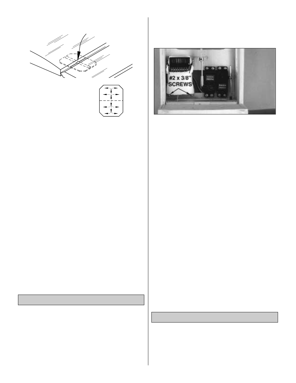
5. Using four #2 x 3/8 screws, mount the receiver tray to
the fuse with the receiver still attached.
❏
6. Mount the receiver switch in a convenient location that
will not interfere with the servos and pushrods inside the
fuselage.
❏
7. Route the receiver antenna. On our prototype we drilled
a small hole in the bottom of the fuse aft of the wing bolt
plate and inserted a piece of tubing to route the antenna
through (fuel tubing or neoprene retractable landing gear air
tubing works well). Make a strain relief from a cut-off servo
arm and place it on the antenna near the receiver as shown
on the plan. Route the antenna through the tubing. Make a
hook out of another cut-off servo arm and loop the end of the
antenna to it. Connect the servo arm hook to a rubber band
and loop it around the tail gear wire.
❏
8. Some modelers prefer to cushion the wing with wing
seating foam tape on the wing saddle of the fuselage. Apply
1/16" seating tape on the wing saddle of the fuselage if
you choose.
❏
9. Prepare the engine compartment for installing the
cowl by connecting the fuel lines, installing the fueling
valve, mounting the muffler, and connecting the throttle
pushrod. Install the cowl, then mount the spinner backplate,
prop, prop washer, and prop nut. Install the spinner.
❏
1. Place the canopy on the fuselage at the location
shown on the plan. Temporarily hold it in position with tape
or rubber bands.
❏
2. Use a felt tip pen to accurately trace the canopy outline
onto the MonoKote film covering. Remove the canopy.
Attach the Canopy
Install the Hardware
THE CA WICKS
ALONG THE "TUNNELS"
TO THE ENTIRE
HINGE SURFACE
ASSEMBLE, THEN APPLY 6 DROPS
OF THIN CA TO CENTER
OF HINGE, ON BOTH SIDES
39