Balance the model, Set the control throws, Channel radio setup – Great Planes CAP 232 40 Kit - GPMA0232 User Manual
Page 40
❏
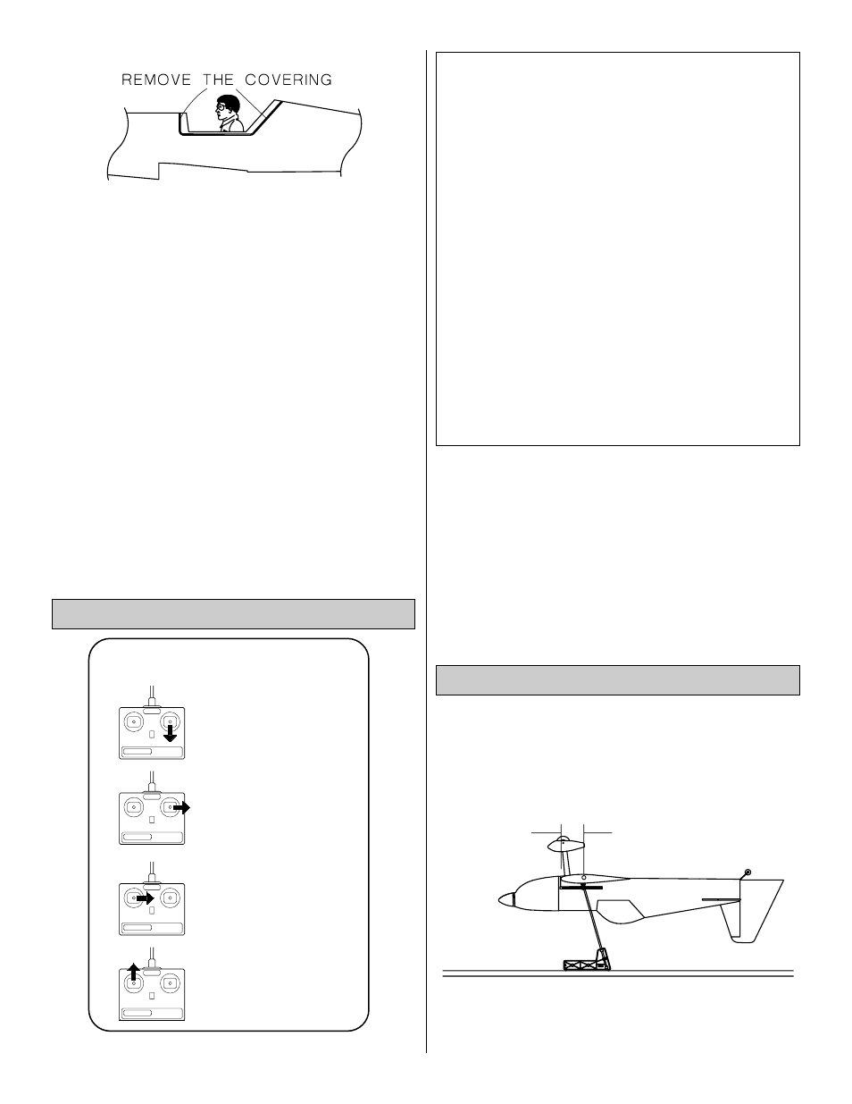
3. Use a sharp #11 blade to
carefully cut the covering
about 1/32" inside of the line you marked without cutting
into the balsa. Wipe away the ink line with a paper towel
lightly dampened with rubbing alcohol.
❏
4. Before you permanently glue the canopy to the
fuselage, securely glue your pilot in place. For the most
security, screw the base of the pilot to the cockpit floor with
two #4 or #6 sheet metal screws from the underside of the
cockpit floor. Place the instrument panel decal on the
instrument panel.
❏
5. Reposition the canopy on the fuselage and confirm
that it covers the exposed wood. Glue the canopy to the
fuselage using rubber bands or masking tape to hold it in
position until the glue dries. We recommend a glue
specifically formulated for gluing on canopies, such as
Pacer "Formula 560" canopy glue. Formula 560 is like
regular white glue (aliphatic resin) in that it dries clear and
cleans-up with water, but it sticks extremely well to butyrate
and dries overnight (to allow for accurate positioning).
NOTE: The balance and control throws for the CAP 232
have been extensively tested. We are confident that
they represent the settings at which the CAP 232 flies
best. Please set up your model to the specifications
listed above. If, after you become comfortable with
your CAP 232, you would like to adjust the throws to
suit your tastes, that's fine. Too much throw can force
the plane into a stall or snap, so remember, "more is
not better." Trust the low rates.
NOTE: This section is VERY important and must NOT
be omitted! A model that is not properly balanced will
be unstable and possibly unflyable.
❏
1. Accurately mark the balance point on the top of the
wing on both sides of the fuselage. Use thin strips of tape
3-3/4"
Balance the Model
We recommend the following control surface throws:
NOTE: The throws are measured at the widest part of
the elevators, rudder, and ailerons. Adjust the position of
the pushrods at the control/servo horns to control the
amount of throw. You may also use the ATV's if your
transmitter has them but the mechanical linkages should
still be set so the ATV's are near 100% for the best servo
resolution (smoothest, most proportional movement).
High Rate
Low Rate
ELEVATOR:
1" up
5/8" up
1" down
5/8" down
RUDDER:
3" right
1-3/4" right
3" left
1-3/4" left
AILERONS:
3/8" up
1/4" up
3/8" down
1/4" down
NOTE: If your radio does not have dual rates, then set
the control surfaces to move at the low rate throws.
CARBURETOR WIDE OPEN
RUDDER MOVES RIGHT
LEFT AILERON MOVES DOWN
RIGHT AILERON MOVES UP
ELEVATOR MOVES UP
4-CHANNEL
TRANSMITTER
(STANDARD MODE 2)
4-CHANNEL RADIO SETUP
TRANSMITTER
4-CHANNEL
TRANSMITTER
4-CHANNEL
TRANSMITTER
4-CHANNEL
Set the Control Throws
40