Great Planes Spirit 2-Meter Sailplane Kit - GPMA0530 User Manual
Page 29
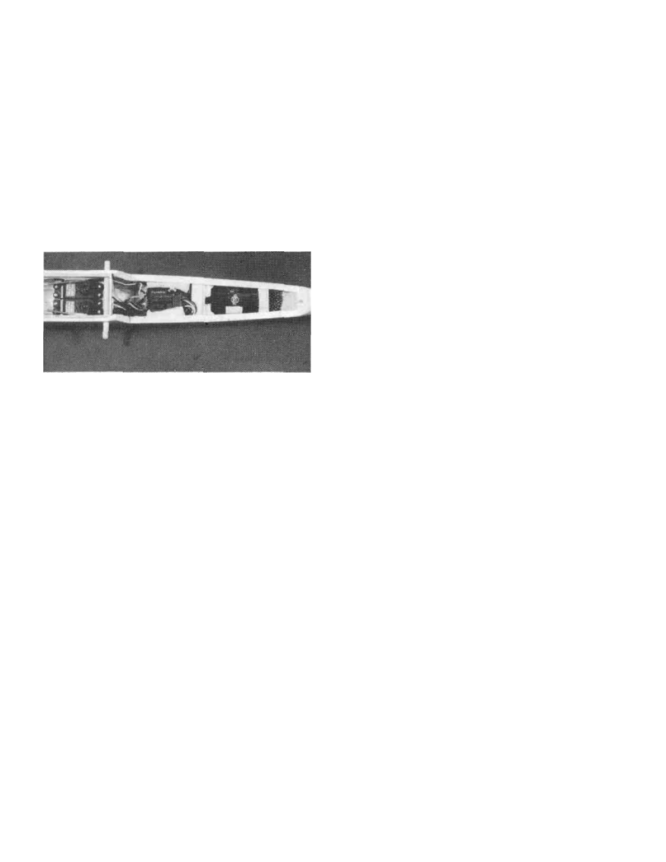
D 8. Pack the receiver in at least 1/4" of foam and install
it in between formers F3 and F4. If you are installing spoilers,
mount the receiver behind the rudder and elevator servos.
The receiver antenna can run down through the fuselage but
try to route it as far away from the servos and servo wires as
possible. Allow the excess antenna to trail from the fuselage.
DO NOT CUT THE ANTENNA!
D 9.
The receiver switch can be taped to former F3 with
double sided foam tape. Because the canopy is so easy to
remove, there is no need for the switch to be accessible from
the outside (this helps cut down on aerodynamic drag and
accidental shut-offs during launching as well).
D 10. The battery pack should be wrapped in 1/4" of foam
also and it should be positioned between formers F2 and F3.
D 11. Hook
up
your radio system and test the operation of
all controls. The controls should move smoothly without any
binding or looseness.
INSTALL THE SPOILERS IN THE WING
(OPTIONAL)
D 1.
Thread a 30" long piece of braided fishing line
through the spoiler tubing in the wing.
D 2.
Thread one end of the string through the small hole
in the spoiler hom and use a piece of a round toothpick to hold
the line in the horn. Allow about 1/2" to hang out the other
side of the horn for fine adjustments.
D 3. Tape the spoiler in position in the wing using a strip
of cellophane, vinyl tape or a strip of covering. The tape
should be flexible enough to allow the spoiler to close on its
own. The tape should also be replaced every once in a
while as it will eventually rip.
D 4.
Glue a small lead weight on the bottom side of the
spoiler to help it close. 1/4 oz. is usually enough since the
airflow will keep the spoilers closed when the plane is flying.
D 5.
Mount the wings on the fuselage and pull the ends of
the spoiler strings up to the spoiler servo. Position the spoiler
servo horn at the rearward end of its swing and wrap one
spoiler string around the screw in the horn. With the spoilers
taped or held closed, apply a drop of thick CA to glue the
string to itself and form a small loop. Remove that string and
perform the same steps to the other string. The two strings
should be the same length (be careful not to glue the two
strings together) and the spoilers should open and close
together. Small adjustments can be made at the toothpick
end if needed.
CONTROL THROWS
We recommend the following CONTROL SURFACE
THROWS:
ELEVATOR:
1/2" up, 1/2" down
RUDDER:
1-1/2" Rt., 1-1/2" Lt
BALANCE THE MODEL
NOTE: This section is VERY important and
must not be omitted! A model that is not properly
balanced will be unstable and possibly unflyable.
NOTE: Throws are measured at the widest part of
the elevator and rudder. These control surface
"throws" are approximate and provide a good
starting point for the first flights with your SPIRIT.
You may wish to change the throws slightly to
provide the smoothness or quickness that you pre-
fer.
Move the pushrod wires (Z-bends, nylon clevises) in
or out on the control horns and servo horns to achieve the
desired movements. If your radio is equipped with' 'endpoint
adjustments" you may set the throws from the transmitter.
D 1.
The balance point (CG-Center of Gravity) is shown
on the plan, and is located under the spar. This is the balance
point at which your model should balance for your first
flights. Later, you may wish to shift the balance up to 3/8"
behind the spar to change the flying characteristics. Moving
the CG forward of the spar will add some stability but it will
decrease the overall performance of the sailplane and make
it stall easier at slower speeds. Moving the balance behind
the spar makes the model more agile with a lighter and
snappier "feel'' and improves the sailplane's response to air
currents. It also makes the model less stable and can cause
the sailplane to "tuck under" or dive when its flying speed
increases. If you fly the SPIRIT with its CG behind the spar
(usually only contest flying), pay close attention and do not
29