Great Planes Spirit 2-Meter Sailplane Kit - GPMA0530 User Manual
Page 12
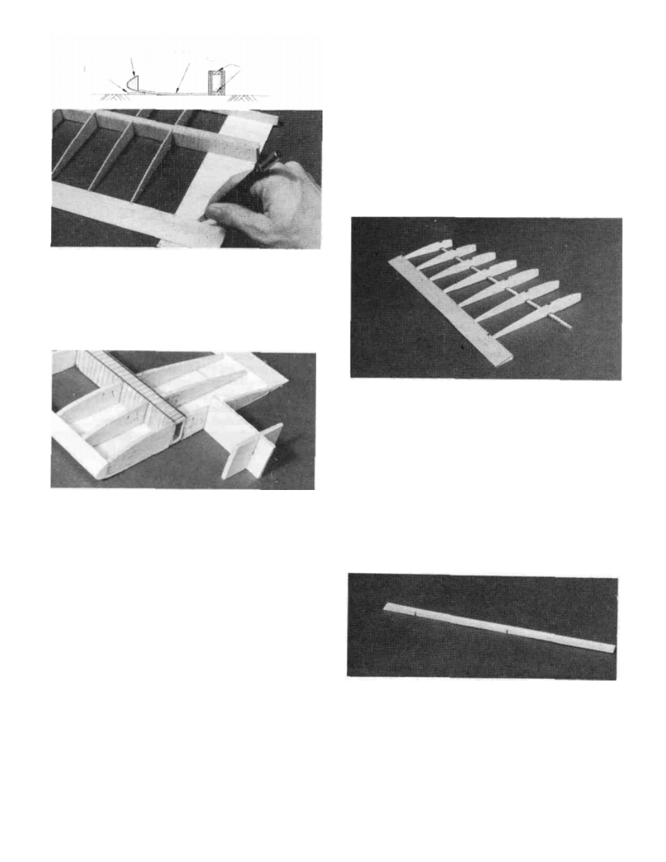
Shaped
balsa LE
1/16" balsa
bottom sheet
DD 20.
Glue another piece to the rear of the joiner box and
then cut a third piece to fit behind the second and glue it in
place.
DD 2 I.Punch out three W1A ribs and three W1B ribs from
the l/8"die-cut balsa rib sheet(SPRTW01). Test fit these ribs
into position. A little sanding may be necessary to make them
fit properly. Glue these ribs into place using thick CA. The
end rib should be tilted in at the top using the slanted end of
the rib gauge to give it the correct angle.
DD 22. Cut and sand the leading edges, trailing edges and
spars to their correct length. Lay the panel over the plans to
determine the correct lengths.
DD 1. Lay one of the Outer Trailing Edges
(SPRTW 12) in place over the plan and cut it to length just past
the last notch. Align the notches in the trailing edge with the
notches on the plans and pin it in position. NOTE: The un-
notched end of this trailing edge will be used later if you
are installing spoilers.
DD 2. "Cross pin" one of the 1/8" x 5/16" x 15-1/8"
Basswood Outer Spars (SPRTW 14) in place.
DD 3.
Punch out the 1/16" (W4-W10) Tip Ribs out of
one of the SPRTW03 die-cut sheets. Glue the ribs in place
with a thick CA at the spar joint and a drop of thin CA at the
trailing edge joint. Use the rib gauge to keep the ribs
perpendicular.
DD 4.
Trial fit the top 1/8" x 5/16" x 15-1/8" Basswood
Outer Spar in place by carefully pressing the spar into the
notches until it is flush with the top of the ribs. Remove the
spar and apply thick CA to the notches. Replace the spar and
allow the glue to cure.
Spars
Work Surface
1/16"
balsa
scrap
BUILD THE OUTER WING PANEL
You'll need the following parts:
SPRTW03
1/16" Die-Cut Balsa Wing Ribs W4 - W10
SPRTW07
1/16" Die-Cut Balsa Shear Webs
SPRTW10
Shaped Balsa Leading Edge
SPRTW 12
Shaped, Notched Balsa Outer Trailing Edge
SPRTW14
1/8" x 5/16" x 15-1/8" Basswood Outer Spars
SPRTW15
7/8" Shaped Balsa Wing Tip Block 12
DD 5. Lay one of the remaining Pre-Shaped Leading
Edges over the LEADING EDGE TEMPLATE at the top
right comer of the plans. Use this drawing as a reference to
cut the leading edge to length and to cut the relief notches. It
is a good idea to cut the leading edge approximately 1/4"
longer on both ends to be on the safe side. It can be cut to
the correct length after it is installed. The relief notches do
not need to go all the way through the leading edge but should
go within 1/8" of doing so. NOTE: You must make a
"Right" and a "Left" L.E.