Figure 3-4 – Cabletron Systems 6000 User Manual
Page 36
Chapter 3: Installation
3-10
6E128-26, 6E138-25, 6E129-26 and 6E139-25 User’s Guide
2.
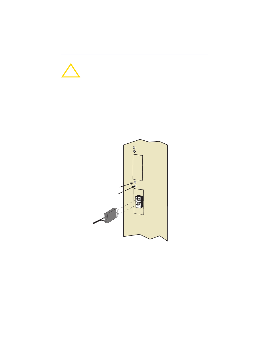
Insert one end of the SC connector into the FE-100FX or FE-100F3
installed in the 6E12X-26. See
3.
At the other end of the fiber optic cable, attach the SC connector to the
other device.
Figure 3-4
FE-100FX and FE-100F3 Port
4.
Verify that a link exists by checking that the port RX LED is on
(flashing amber, blinking green, or solid green). If the RX LED is off
and the TX LED is not blinking amber, perform the following steps
until it is on:
!
CAUTION
Do not touch the ends of the fiber optic strands, and do not let
the ends come in contact with dust, dirt, or other contaminants.
Contamination of the ends causes problems in data
transmissions. If the ends become contaminated, blow the
surfaces with a canned duster. A fiber port cleaning swab
saturated with optical-grade isopropyl alcohol may also be used
to clean the ends.
25
26
FE-100FX
RX LED
TX LED
- 2E42-27R (164 pages)
- 6H122-16 (158 pages)
- 24 (35 pages)
- 9T427-16 (16 pages)
- bridges (132 pages)
- CSX200 (88 pages)
- 2208 (158 pages)
- SM-CSI1076 (69 pages)
- SEHI-22 (93 pages)
- 9T425-16 (40 pages)
- 1800 (448 pages)
- ESX-1380 (86 pages)
- DLE23-MA (202 pages)
- 2E43-51 (168 pages)
- 5000 (83 pages)
- 6H253-13 (62 pages)
- Lancast Media Converter 7000 (108 pages)
- SmartCell 6A000 (102 pages)
- 9G421-02 (12 pages)
- SEH-22 (56 pages)
- 9A000 (180 pages)
- SEH-24 (64 pages)
- 6E123-26 (184 pages)
- STS16-20R (258 pages)
- 2E43-27 (164 pages)
- Cabletron MicroLAN 9E132-15 (36 pages)
- 9F120-08 (28 pages)
- 9E428-36 (18 pages)
- Device Management Module Dec GigaSwitch (65 pages)
- ELS10-26TX (18 pages)
- MICROMMAC-22T (105 pages)
- CSX1200 (644 pages)
- 7H02-06 (36 pages)
- 150 (106 pages)
- 9F206-02 (10 pages)
- MMAC-Plus 9T122-24 (27 pages)
- SEH100TX-22 (52 pages)
- 7C03 MMAC (16 pages)
- 2H253-25R (64 pages)
- TRXI-42 (92 pages)
- 7C04 (150 pages)
- 2H22 (120 pages)
- 2000 (196 pages)
- 7C04 Workgroup (25 pages)