Drawmer M500 Dynamics Processor User Manual
Page 18
M500 OPERATORS MANUAL
Ch 3 - 12
To avoid possible confusion as regards the LINK settings,
especially in the cases of the more advanced Effects, it is
recommended that the user experiment with a preset patch which
includes the desired linked Effect and make tiny adjustments,
rather than attempting 'Linked Effects' from scratch.
FILTER
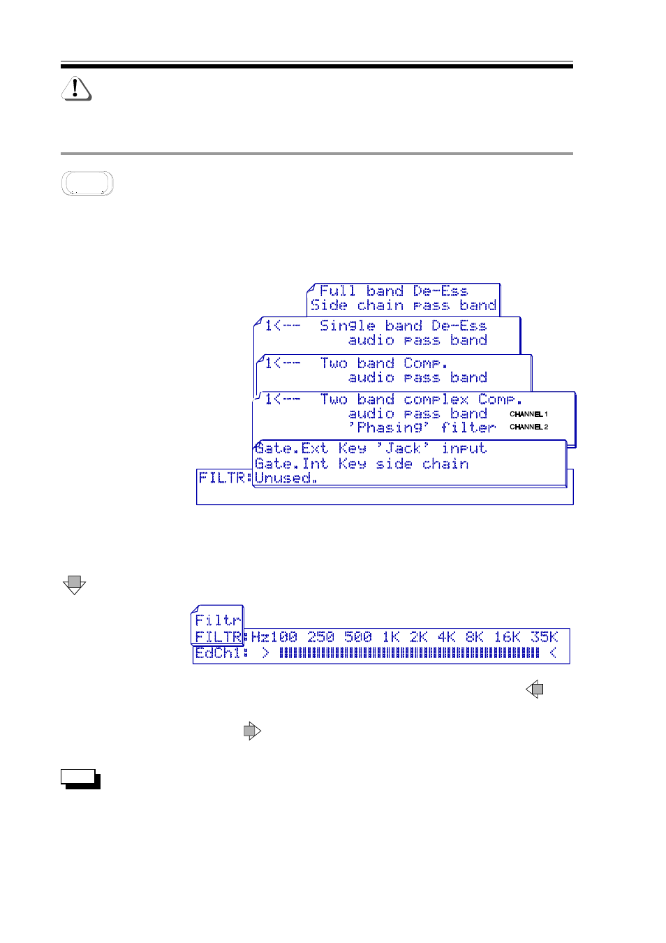
Primary function: Side chain filter for GATE and DE-ESSER. If the FILTER is assigned to either the
DE-ESSER or the GATE, the top display page will show where the filter is 'patched' (ie. where it
is placed in the chain) and how it its functioning, otherwise the display will read:
Unused
Unused. For the
more complex DE-ESSING functions, the display alters for each channel depending on whether
the pass-band or stop-band is being veiled/edited.
THE MANY POSSIBLE FILTER VIEW
DISPLAYS EXPLAINING FILTER
USAGE AND FUNCTION
The method of display of filter pass band is a bargraph beneath a frequency scale showing the
upper and lower cutoff limits of the filter. More filter cut-off frequencies are present than are
shown on the upper scale due to the limitations of the LCD.
DOWN
THE FILTER DISPLAY
FILTER Low Frequency
To adjust pass-band frequency, it is necessary only to hit
LEFT
and then use the rotary controller.
FILTER High Frequency
Hit
RIGHT arrow and use the controller to adjust the upper
frequency setting.
Notice the lefthand word
FILTR
FILTR in UPPER case. This page and the
FILTR
page below are identical except that the signal monitored at the
output of the M500 is different. On this page, the monitor signal
is the filter output which functions in much the same way as the
'side-chain listen' facility used on traditional frequency-conscious
gates. eg DRAWMER DS201.