Drawmer M500 Dynamics Processor User Manual
Page 14
M500 OPERATORS MANUAL
Ch 3 - 8
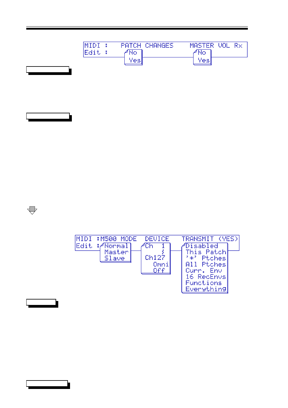
THIRD MIDI PARAMETER DISPLAY
When set to
YES
YES, allows the M500's 128 patches to be remotely
PATCH CHANGES
selected and loaded ready for use over MIDI using standard MIDI
program change messages. When the
NO
NO option is selected, the
M500 will not respond to incoming program changes, but all other
relevant MIDI information will still be accepted. This parameter
setting is also repeated within the PATCH screens, which is
another obvious location to need to adjust this parameter.
MASTER VOLUME set to
YES
YES enables the output gain of the M500
MASTER VOLUME
to be controlled by MIDI controller 7, "master volume". The actual
output gain display in dBs is only updated when the OUTPUT page
is constantly accessed, and any adjustment of the rotary controller
will revert the gain between
-20db
-20db and
+20dB
+20dB. The MIDI "master
volume" data value is scaled to operate between
-90dB
-90dB and
+20dB
+20dB. A data value of 110 (06E hex) or above, will set the output
gain to +20dB and a value of 0 will set the gain to -90dB. The
formulae for setting output gain is:
OUTPUT GAIN (in dBs) = DATA VALUE - 90
An example of a valid MIDI instruction to alter the output gain
would be:
Controller Status + Channel Number
B0 hex
Master volume (Controller) Number 07
Controller Data (eg set 0dB)
5A hex 90 dec
DOWN
The fourth (bottom) page covers M500 MODE, DEVICE and
TRANSMIT.
THE FOURTH MIDI PARAMETER DISPLAY
M500 MODE section enables more than one M500 to be used in
M500 MODE
the same MIDI system; if only a single M500 is in use, this should
be left set to
NORMAL
NORMAL. The other options are
MASTER
MASTER and
SLAVE
SLAVE.
In a multiple M500 setup keypad and rotary control on a master
unit can be echoed on other slave units. Within one MIDI
connection circuit, only one unit should be configured as
MASTE
MASTE
R
R
with all other units wishing to be communicated with being set to
SLA
SLA
VE
VE. It is important that all communicating M500's be set so
that matching audio channels have to identical MIDI channels for
both audio channels. For example, if the
MASTER
MASTER unit has the left
audio channel set to MIDI channel 4, then so should all the
SLAV
SLAV
E
E
units. The right audio channels should be set to a different MIDI
channel.
DEVICE parameter selects the 'Exclusive data' channel number
DEVICE NUMBER