Digilent FX12 User Manual
Page 9
Digilent
FX12 Reference Manual
www.digilentinc.com
Copyright Digilent, Inc.
Page 9/18
Doc: 502-046
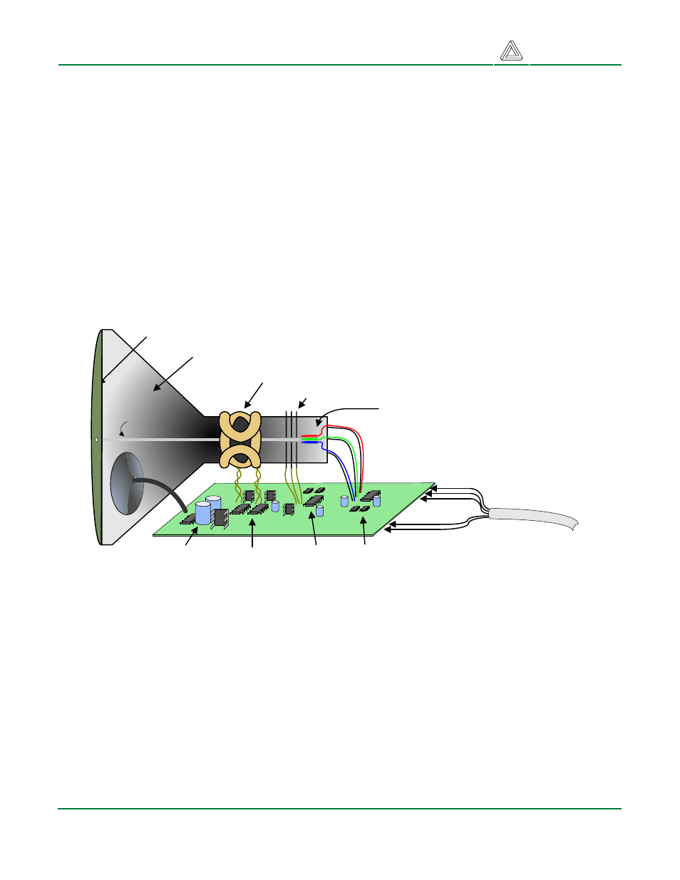
Cathode Ray Tube
Display System
Anode (entire screen)
High voltage
supply (>20kV)
Deflection coils
Grid
Electron guns
(Red, Blue, Green)
gun
control
grid
control
deflection
control
R,G,B signals (to guns)
Sync signals
(to deflection control)
Cathode ray tube
Cathode ray
VGA cable
VGA System Timing
CRT-based VGA displays use amplitude-modulated moving electron beams (or cathode rays) to
display information on a phosphor-coated screen. LCD displays use an array of switches that can
impose a voltage across a small amount of liquid crystal, thereby changing light permitivity through
the crystal on a pixel-by-pixel basis. Although the following description is limited to CRT displays, LCD
displays have evolved to use the same signal timings as CRT displays (so the “signals” discussion
below pertains to both CRTs and LCDs). Color CRT displays use three electron beams (one for red,
one for blue, and one for green) to energize the phosphor that coats the inner side of the display end
of a cathode ray tube (see illustration). Electron beams emanate from “electron guns”, which are
finely-pointed heated cathodes placed in close proximity to a positively charged annular plate called a
“grid”. The electrostatic force imposed by the grid pulls rays of energized electrons from the cathodes,
and those rays are fed by the current that flows into the cathodes. These particle rays are initially
accelerated towards the grid, but they soon fall under the influence of the much larger electrostatic
force that results from the entire phosphor-coated display surface of the CRT being charged to 20kV
(or more). The rays are focused to a fine beam as they pass through the center of the grids, and then
they accelerate to impact on the phosphor-coated display surface. The phosphor surface glows
brightly at the impact point, and the phosphor continues to glow for several hundred microseconds
after the beam is removed. The larger the current fed into the cathode, the brighter the phosphor will
glow.
Between the grid and the display surface, the beam passes through the neck of the CRT where two
coils of wire produce orthogonal electromagnetic fields. Because cathode rays are composed of
charged particles (electrons), they can be deflected by these magnetic fields. Current waveforms are
passed through the coils to produce magnetic fields that interact with the cathode rays and cause
them to transverse the display surface in a “raster” pattern, horizontally from left to right and vertically
from top to bottom. As the cathode ray moves over the surface of the display, the current sent to the
electron guns can be increased or decreased to change the brightness of the display at the cathode
ray impact point.