Vga display surface – Digilent FX12 User Manual
Page 10
Digilent
FX12 Reference Manual
www.digilentinc.com
Copyright Digilent, Inc.
Page 10/18
Doc: 502-046
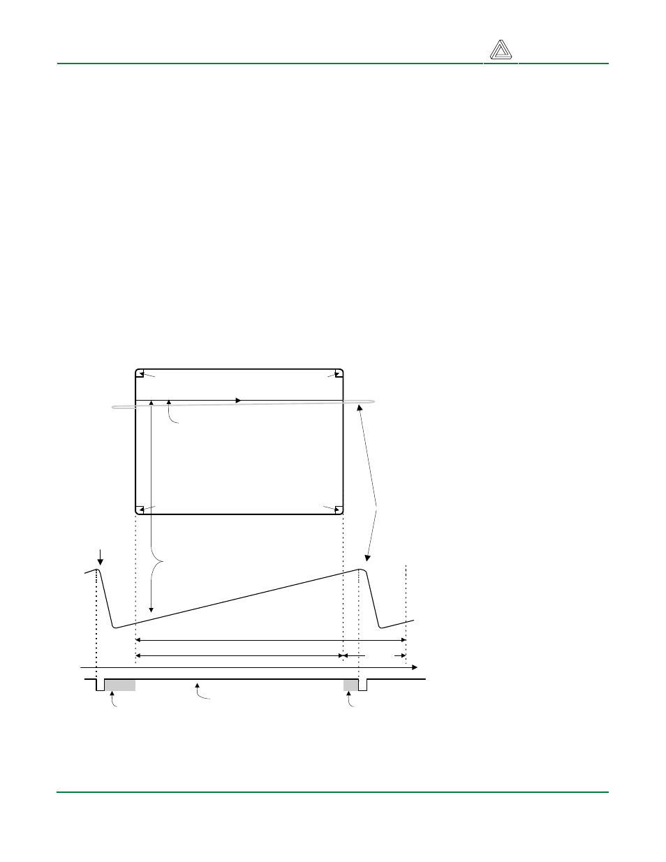
Information is only displayed when the beam is moving in the “forward” direction (left to right and top
to bottom), and not during the time the beam is reset back to the left or top edge of the display. Much
of the potential display time is therefore lost in “blanking” periods when the beam is reset and
stabilized to begin a new horizontal or vertical display pass. The size of the beams, the frequency at
which the beam can be traced across the display, and the frequency at which the electron beam can
be modulated determine the display resolution. Modern VGA displays can accommodate different
resolutions, and a VGA controller circuit dictates the resolution by producing timing signals to control
the raster patterns. The controller must produce synchronizing pulses at 3.3V (or 5V) to set the
frequency at which current flows through the deflection coils, and it must ensure that video data is
applied to the electron guns at the correct time. Raster video displays define a number of “rows” that
corresponds to the number of horizontal passes the cathode makes over the display area, and a
number of “columns” that corresponds to an area on each row that is assigned to one “picture
element” or pixel. Typical displays use from 240 to 1200 rows and from 320 to 1600 columns. The
overall size of a display and the number of rows and columns determines the size of each pixel.
Video data typically comes from a video refresh memory, with one or more bytes assigned to each
pixel location (the FX12 uses 8-bits per pixel). The controller must index into video memory as the
beams move across the display, and retrieve and apply video data to the display at precisely the time
the electron beam is moving across a given pixel.
A VGA controller circuit
must generate the HS and
VS timings signals and
coordinate the delivery of
video data based on the
pixel clock. The pixel clock
defines the time available
to display one pixel of
information. The VS signal
defines the “refresh”
frequency of the display,
or the frequency at which
all information on the
display is redrawn. The
minimum refresh
frequency is a function of
the display’s phosphor and
electron beam intensity,
with practical refresh
frequencies falling in the
50Hz to 120Hz range. The
number of lines to be
displayed at a given
refresh frequency defines
the horizontal “retrace”
frequency. For a 640-pixel
by 480-row display using a 25MHz pixel clock and 60 +/-1Hz refresh, the signal timings shown in the
table below can be derived. Timings for sync pulse width and front and back porch intervals (porch
intervals are the pre- and post-sync pulse times during which information cannot be displayed) are
based on observations taken from actual VGA displays.
Current
through
horizontal
defletion
coil
Stable current ramp - information
displayed during this time
Retrace - no
information
displayed
during this
time
Total horizontal time
Horizontal display time
Horizontal sync signal
sets retrace frequency
retrace
time
time
HS
"back porch"
"front porch"
VGA display
surface
640 pixels are displayed each
time the beam travels across
the screen
pixel 0,639
pixel 0,0
pixel 479,0
pixel 479,639