Digilent FX12 User Manual
Page 7
Digilent
FX12 Reference Manual
www.digilentinc.com
Copyright Digilent, Inc.
Page 7/18
Doc: 502-046
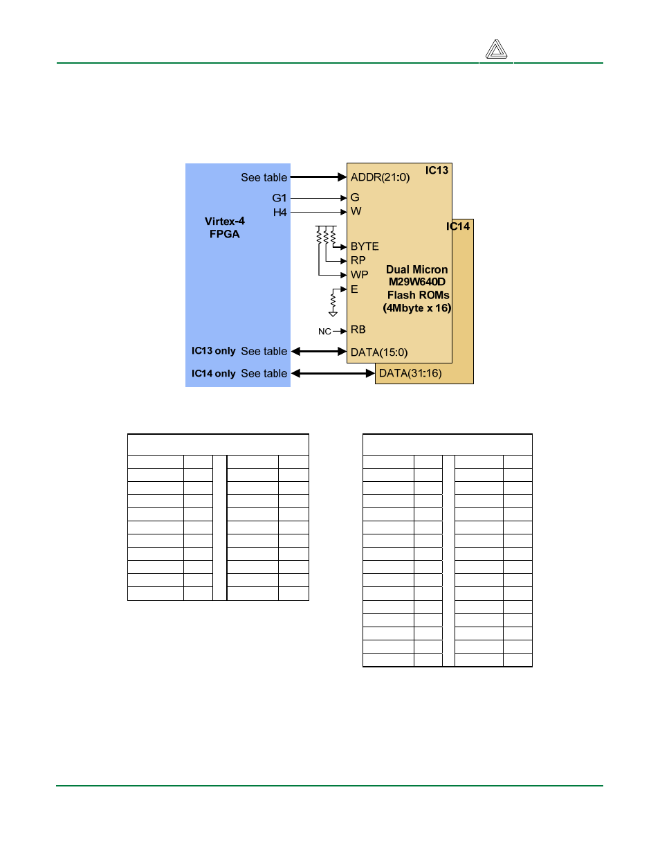
Flash Memory
The FX12 contains two Micron M29W64OD 4Mbyte Flash devices, for a total of 8Mbytes. The Flash
array is organized as a 2M x 32 array, with all control signals routed in parallel to the two devices.
Flash Address Pins
Flash Data Pins
ADDR21 H3
ADDR10 D3
DATA31 A6 DATA15 H2
ADDR20 G4
ADDR9 E3
DATA30
A5 DATA14
J2
ADDR19 F3
ADDR8 F4
DATA29
B4 DATA13
K1
ADDR18 J4
ADDR7 K4
DATA28
B3 DATA12
L1
ADDR17 J3
ADDR6 K3
DATA27
C2 DATA11
M2
ADDR16 C6
ADDR5 L4
DATA26
D2 DATA10
F5
ADDR15 C5
ADDR4 M3
DATA25
E1 DATA9 H5
ADDR14 D5
ADDR3 M4
DATA24
F1 DATA8
J5
ADDR13 C4
ADDR2 L5
DATA23
B6 DATA7
H1
ADDR12 D4
ADDR1 M5
DATA22
B5 DATA6
K2
ADDR11 C11
ADDR0 M6
DATA21
A3 DATA5
L2
DATA20
B2 DATA4
M1
DATA19
C1 DATA3
E5
DATA18
E2 DATA2
G5
DATA17
F2 DATA1
J6
DATA16
G2 DATA0
K5
VGA Port
The five standard VGA signals Red, Green, Blue, Horizontal Sync (HS), and Vertical Sync (VS)
available at the VGA connector arise from the FPGA (sync signals) and an Analog Devices ADV7125
high speed video DAC (color signals). The video DAC presents three parallel 8-bit data ports to the
FX12 Flash Circuit Diagram